Method for carrying out wave beam formation, device and base station

A beamforming and base station technology, applied in the field of communication, can solve problems such as peak false alarms, amplitude distortion, and performance loss, and achieve the effects of reducing power consumption, increasing processing performance, and reducing complexity

Inactive Publication Date: 2017-03-22
ALCATEL LUCENT SHANGHAI BELL CO LTD
View PDF5 Cites 3 Cited by
  • Summary
  • Abstract
  • Description
  • Claims
  • Application Information

AI Technical Summary

Problems solved by technology

[0024] The above solution has a cyclic shift restriction, which limits the number of ZC sequences with the same root
On the other hand, there is also amplitude distortion in the PDP of the mask window, which may introduce some performance loss. For high-speed cells, the distortion introduced by the Doppler frequency shift to the PDP is more likely to lead to peak false alarms

Method used


Image

  • Method for carrying out wave beam formation, device and base station
  • Method for carrying out wave beam formation, device and base station
  • Method for carrying out wave beam formation, device and base station

Examples


Embodiment Construction

[0051] The present invention will be described in further detail below in conjunction with the accompanying drawings.

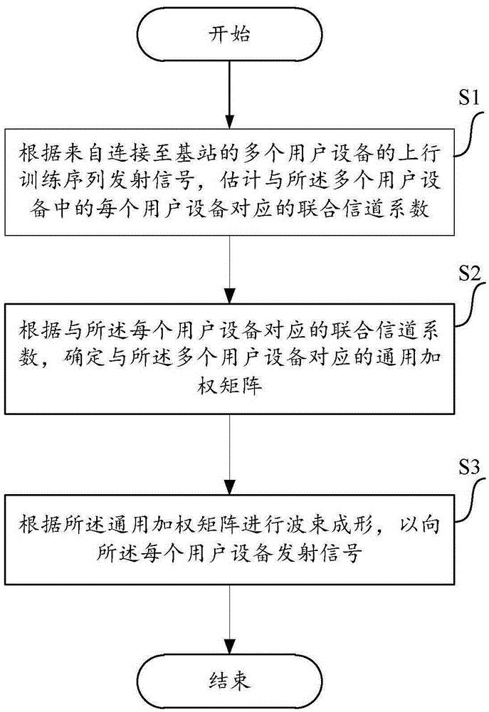
[0052] figure 1 It is a schematic flowchart of a method for performing beamforming in a high-speed rail mobile communication system according to an embodiment of the present invention.

[0053] Wherein, the method of this embodiment is mainly realized by the base station in the high-speed rail mobile communication system. Wherein, the high-speed rail mobile communication system is a communication system applied on high-speed rail; preferably, the high-speed rail mobile communication system is an LTE system; more preferably, the high-speed rail mobile communication system is an LTE TDD system.

[0054] It should be noted that the base station and the high-speed rail communication system are only examples. If other existing or future base stations and high-speed rail communication systems are applicable to the present invention, they should also be included in...


PUM


Abstract

The invention provides a method for carrying out wave beam formation in a high-speed rail mobile communication system. The method comprises steps of a, according to uplink training sequences of multiple user equipment connected to a base station, estimating a united channel coefficient corresponding to each user equipment in multiple user equipment; b, according to the united channel coefficient corresponding to each user equipment, determining universal weighting matrixes corresponding to the multiple user equipment; and c, according to the universal weighting matrixes, carrying out wave beam formation so as to emit signals to each user equipment. The invention also provides a scheme for carrying out PRACH detection in the high-speed rail mobile communication system. According to the invention, the universal weighting matrixes can be used for carrying out wave beam formation on all user equipment on a high-speed rail without determining the weighting matrix corresponding to each user equipment; and in addition, uplink emission information of online user equipment are adopted to correct frequency shift of user equipment initiating the PRACH before the PRACH detection.

Description

technical field [0001] The present invention relates to the field of communication technologies, in particular to a method, device and base station for beamforming in a high-speed rail mobile communication system. Background technique [0002] Multiple-input-multiple-output (MIMO) is a key physical layer technology in 3GPP Long Term Evolution (LTE), and beamforming technology is one of the main technologies in the physical layer of communication systems, especially For a time division duplex (Time Division Duplex, TDD for short) system. [0003] At present, for each user equipment connected to the base station, the base station estimates the uplink channel coefficient of the user equipment according to the uplink training signal (for example, assuming that the eNodeB has N B antennas, and the UE has N U , uplink channel coefficient Among them, H UL is N B ×N U matrix), and through corresponding algorithms, such as Singular Value Decomposition (SVD), Eigenvalue Based B...

Claims


Application Information

Patent Timeline
Patent Type & Authority Applications(China)
IPC IPC(8): H04B7/0413H04B7/06
CPCH04B7/0413H04B7/0617
Inventor 吴涛李剑飞王新勇
Owner ALCATEL LUCENT SHANGHAI BELL CO LTD
Why Eureka
Try Eureka