
Channel recording method and device

A channel and slicing technology, applied in the field of communication, can solve problems such as increasing system complexity, increasing hardware costs and maintenance costs, and achieve the effect of reducing complexity

Active Publication Date: 2017-03-22
北京数码视讯软件技术发展有限公司
View PDF4 Cites 1 Cited by
  • Summary
  • Abstract
  • Description
  • Claims
  • Application Information

AI Technical Summary

Problems solved by technology

[0007] Need to add a new server for forwarding, which increases the complexity of the system, increases the hardware cost and maintenance cost

Method used


Image

  • Channel recording method and device
  • Channel recording method and device
  • Channel recording method and device

Examples


no. 1 example

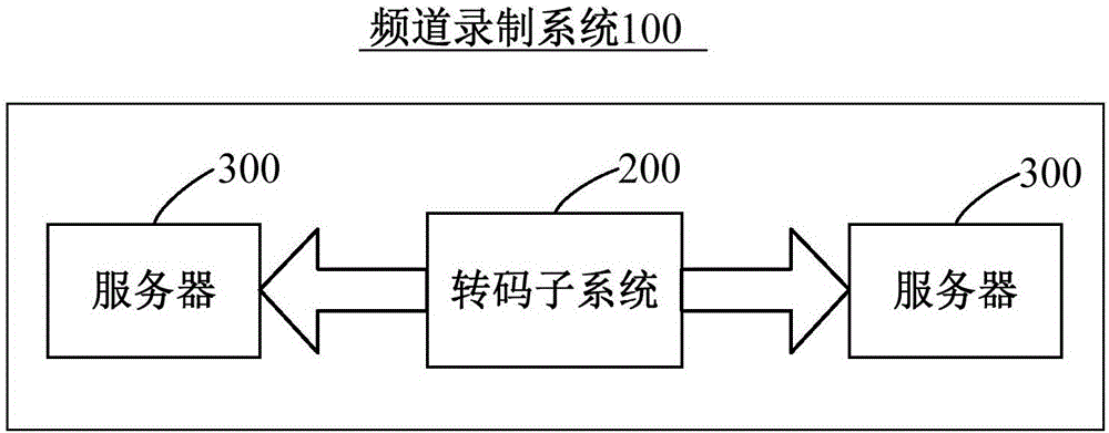
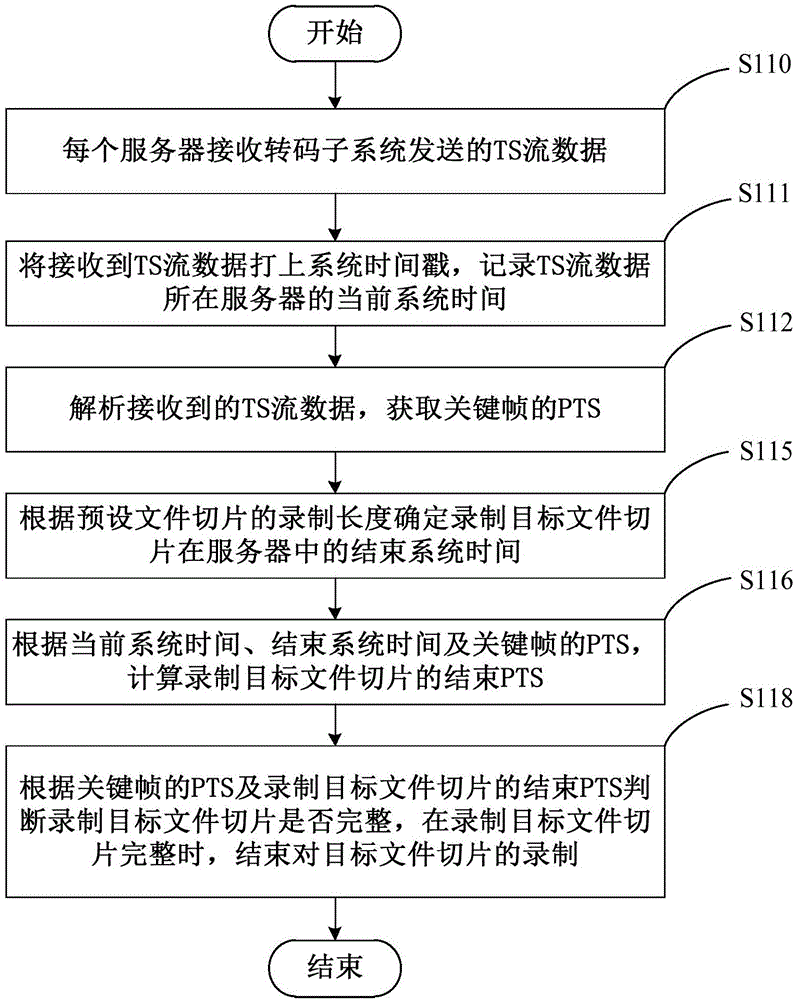
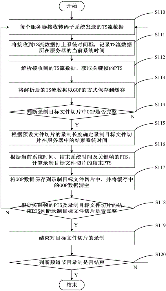
[0038] see figure 2 , figure 2 It is a schematic flowchart of the main steps of the channel recording method provided by the preferred embodiment of the present invention. The method is applied to a plurality of servers 300 of the channel recording system 100, and the clocks of the plurality of servers 300 are synchronized, and the channel recording system 100 also includes a transcoding subsystem 200 communicatively connected with the plurality of servers 300, the following The specific process of the channel recording method is described in detail.

[0039] Step S110 , each server 300 receives the TS stream data sent by the transcoding subsystem 200 .

[0040]In this embodiment, the transcoding subsystem 200 preferably uses the UDP protocol to transmit the TS stream data information to the server 300 in a multicast manner. During IP network data transmission, generally there are three modes: unicast, multicast and broadcast. In this embodiment, the multicast mode is pre...

no. 2 example

[0074] see Figure 4 , Figure 4 The block diagram of the main functional modules of the channel recording device 400 provided by the preferred embodiment of the present invention. The channel recording device 400 is applied to multiple servers 300 of the channel recording system 100 , and the clocks of the multiple servers 300 are synchronized. The channel recording system 100 also includes a transcoding subsystem 200 communicatively connected to the multiple servers 300 . The channel recording device 400 mainly includes a receiving module 410 , a recording module 420 , an analyzing module 430 , a determining time module 440 , a calculating module 450 , and a first judging module 460 .

[0075] The receiving module 410 is configured for each server 300 to receive the TS stream data sent by the transcoding subsystem 200 .

[0076] The recording module 420 is configured to stamp the received TS stream data with a system time stamp, and record the current system time of the se...


PUM


Abstract

The invention provides a channel recording method and device. The method comprises the following steps of: receiving TS stream data sent by a transcoding sub-system by each server; marking a system timestamp on the received TS stream data, and recording the current system time of the server, where the TS stream data is; analyzing the received TS stream data to obtain the PTS of a key frame; according to the recording length of a pre-set file section, determining the ending system time of a recorded target file section in the server; according to the current system time, the ending system time and the PTS of the key frame, calculating the ending PTS of the recorded target file section; and, according to the PTS of the key frame and the ending PTS of the recorded target file section, judging whether the recorded target file section is complete or not, and, when the recorded target file section is complete, ending recording of the target file section. By means of the method and the device, simultaneous recording of multiple servers can be realized; recorded contents can be consistent; a transit server is unnecessary; and thus, the hardware cost and the maintenance cost are reduced.

Description

technical field [0001] The present invention relates to the technical field of communication, in particular, to a channel recording method and device. Background technique [0002] The recording of live channels is an important function of the video playback system. Through the recording of live channels, services such as time shift and playback are provided, and users can freely arrange time to watch live TV programs, which provides users with great viewing convenience . [0003] Live channel recording backup refers to recording the same channel through two or more recording servers at the same time. When a recording server has an abnormality, it will not affect the overall business. When multiple recording servers record at the same time, it is necessary to ensure the consistency of the recorded content of multiple recording servers, that is, the requirements for the saved file slices and index files are completely consistent, otherwise there will be screen duplication an...

Claims


Application Information

Patent Timeline
IPC IPC(8): H04L29/06H04N21/231H04N21/236H04N21/242H04N21/8547
CPCH04N21/23116H04N21/23602H04N21/23608H04N21/242H04N21/8547H04L65/75
Inventor 杨大维吴畏梁云唐平
Owner 北京数码视讯软件技术发展有限公司
Learn More