
Video signal detection method and device

A technology of video signal and detection method, which is applied in the computer field, can solve the problems of blurred screen, black screen of display screen, TV system cannot quickly enter the video playback stage, etc., so as to avoid black screen or blurred screen and improve stability

Active Publication Date: 2017-03-22
HISENSE VISUAL TECH CO LTD
View PDF9 Cites 2 Cited by
  • Summary
  • Abstract
  • Description
  • Claims
  • Application Information

AI Technical Summary

Problems solved by technology

[0004] In order to ensure the stability of the TV system, the existing video signal receiving module strictly detects the received video signal and locks the video signal only after the video signal is completely stable. Therefore, the TV system cannot quickly enter the video playback stage. When there are fluctuations due to interference, it is also easy to fall into a cycle where the signal cannot be locked and the video signal is always detected; the existing video signal receiving module will no longer detect the resolution of the video signal after the video signal is locked. Therefore, when the video signal is in When an abnormal signal occurs, it may also cause a black screen or a blurred screen on the display, reducing the stability of the TV system

Method used


Image

  • Video signal detection method and device
  • Video signal detection method and device
  • Video signal detection method and device

Examples


Embodiment Construction

[0044] In order to make the purpose, technical solutions and advantages of the embodiments of the present invention clearer, the technical solutions in the embodiments of the present invention will be clearly and completely described below in conjunction with the drawings in the embodiments of the present invention. Obviously, the described embodiments It is a part of embodiments of the present invention, but not all embodiments. Based on the embodiments of the present invention, all other embodiments obtained by persons of ordinary skill in the art without creative efforts fall within the protection scope of the present invention.

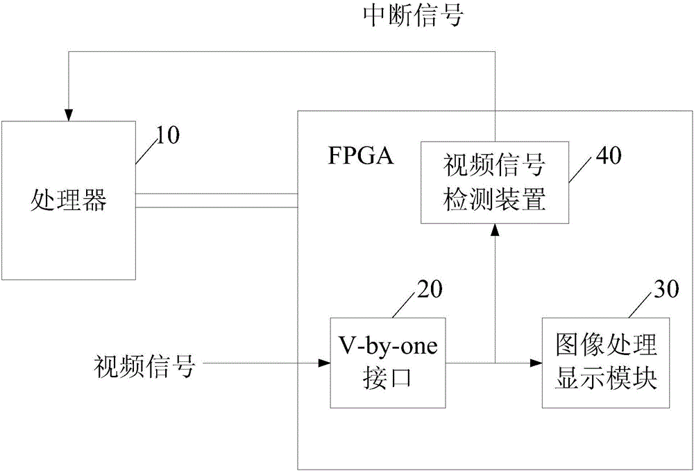
[0045] figure 1 It is a schematic diagram of the system architecture of FPGA-based laser TV. Such as figure 1 As shown, the system architecture of the FPGA-based TV includes a processor 10 , a V-by-one interface 20 , an image processing and display module 30 and a video signal detection device 40 . The processor 10 communicates with the V-by-on...


PUM


Abstract

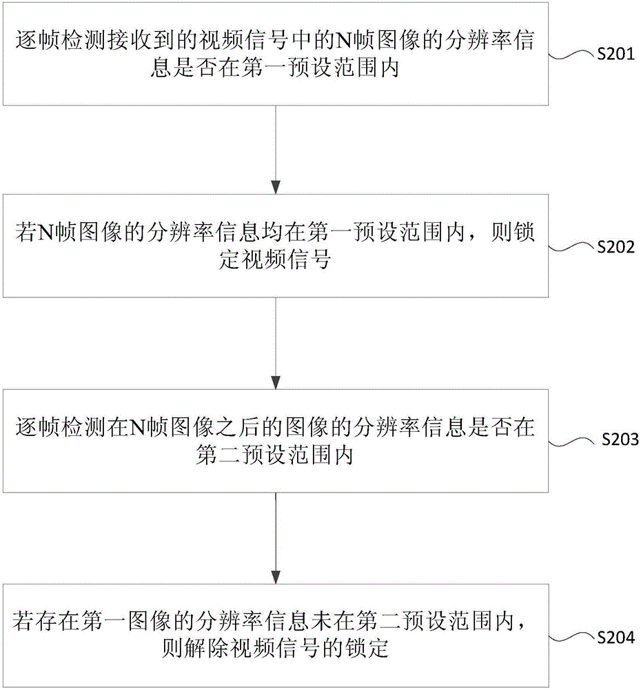
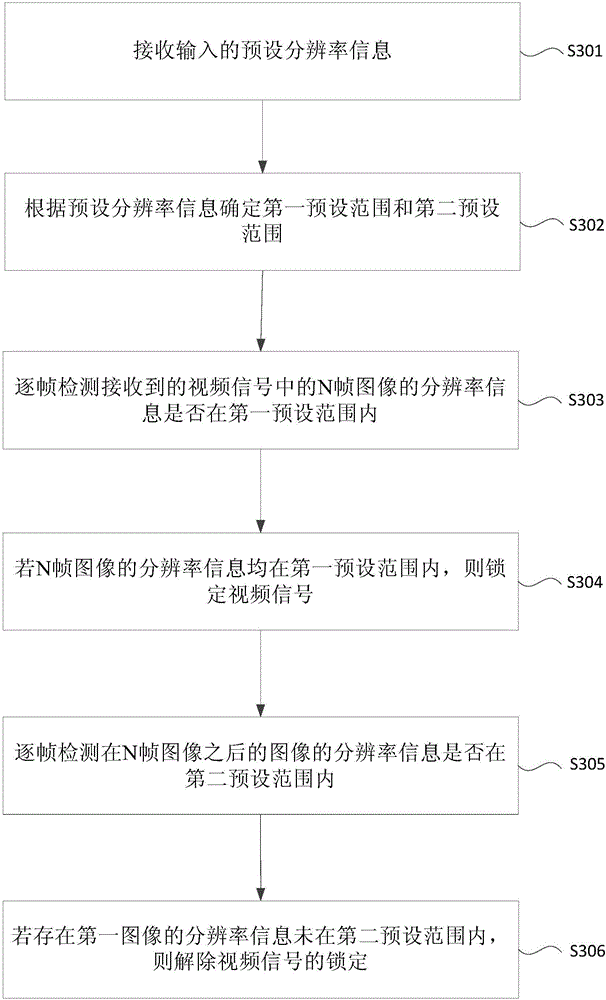
The present invention provides a video signal detection method and device. The method comprises the steps of detecting whether the resolution information of N frames of images in a received video signal is within a first preset range frame by frame; if yes, locking the video signal; detecting whether the resolution information of the images after the N frames of images is within a second preset range frame by frame; if not, unlocking the video signal, wherein the first preset range is greater than the second preset range, and N is a positive integer greater than 1. According to the video signal detection method provided by the present invention, a television system can enter a video playing stage rapidly, and the change of the resolution of the images can be detected timely, thereby avoiding a blank screen or a broken screen, and further improving the stability of the television system.

Description

technical field [0001] The invention relates to computer technology, in particular to a video signal detection method and device. Background technique [0002] A TV system usually includes a video signal receiving module and an image processing and display module. The video signal receiving module receives the video signal frame by frame, and locks the video signal when it is determined that the image resolution of the received video signal matches the preset image resolution. When the video signal is locked, the video signal receiving module sends the received image to the image processing and display module, and the image processing and display module performs image processing and display according to the preset image resolution. [0003] When the resolution of the image received by the image processing and display module is inconsistent with the preset resolution, it may cause a blurry or black screen on the display screen, requiring the entire TV system to be restarted,...

Claims


Application Information

Patent Timeline
Patent Type & Authority Applications(China)
IPC IPC(8): H04N17/00
CPCH04N17/004
Inventor 徐卫夏建龙刘西富
Owner HISENSE VISUAL TECH CO LTD
Learn More