
Forced air cooling chassis resisting marine atmospheric environment

A marine atmosphere, air-cooled machine technology, applied in electrical components, electrical equipment structural parts, cooling/ventilation/heating transformation and other directions, can solve the problems of dust accumulation, corrosion, affecting the cooling effect of equipment, etc., to reduce the difficulty of work , to avoid the effect of dust accumulation and corrosion

Inactive Publication Date: 2017-03-22
CHINA AVIATION OPTICAL-ELECTRICAL TECH CO LTD
View PDF4 Cites 1 Cited by
  • Summary
  • Abstract
  • Description
  • Claims
  • Application Information

AI Technical Summary

Problems solved by technology

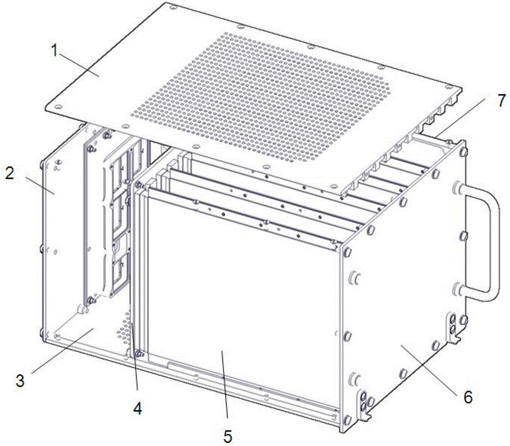
[0005] Disadvantages: The sub-board 5 and the back board 4, including the electronic components on them, are directly in contact with the cooling gas and the outside atmosphere. After long-term use, dust accumulation and corrosion will occur. Excessive dust accumulation will affect the cooling effect of the equipment, and corrosion will cause the chassis to The anti-corrosion performance of the equipment decreases, and when the equipment is used in the marine atmosphere environment, the corrosion will be more rapid
At the same time, during the later cleaning and maintenance, because the dust will enter the sub-board 5 and the backplane 4 and adhere to the components, it is very difficult to clean

Method used


Image

  • Forced air cooling chassis resisting marine atmospheric environment
  • Forced air cooling chassis resisting marine atmospheric environment
  • Forced air cooling chassis resisting marine atmospheric environment

Examples


Embodiment Construction

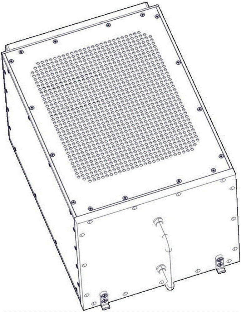
[0020] Such as Figure 3-5 As shown, a forced air-cooled chassis resistant to marine atmospheric environment includes an upper cover plate 1, a rear panel 2, a lower cover plate 3, a front panel 6, a right side plate 7 and a left side plate 8, and the upper cover plate 1 And the lower cover plate 3 has cooling holes for cooling air to enter and exit, it is characterized in that: the forced air cooling cabinet also includes a left cold plate 9, a right cold plate 10, a top plate 11 and a bottom plate 12, by the front panel 6, the rear panel 2. The left cold plate 9, the right cold plate 10, the top plate 11 and the bottom plate 12 constitute the main body of the case with a closed structure, and the upper cover plate 1, the lower cover plate 3, the right side plate 7 and the left side plate 8 cover the outside of the main body of the case , and the left cold plate 9 and the right cold plate 10 have cooling air passages communicating with the upper cover plate 1 and the lower co...


PUM


Abstract

The invention belongs to the forced air cooling technology of an electronic device, and in particular relates to a forced air cooling chassis resisting marine atmospheric environment. Electronic components on the existing forced air cooling chassis directly contact cooling gas and outside atmosphere, and suffer to dust and corrosion after long-term use. Excessive dust affects the cooling effect of the device. The degradation of the three-proofing performance of the chassis is caused by corrosion. According to the invention, the chassis structure is redesigned; the chassis main body in a closed structure is composed of a front panel, a rear panel, a left cooling plate, a right cooling plate, a top plate and a bottom plate; the chassis main body is covered by an upper cover plate, a lower cover plate, a right side plate and a left side plate; the left cooling plate and the right cooling plate are provided with cooling air passages which are communicated with the upper cover plate and the lower cover plate; and on the premise that ventilation, cooling and other performances of the electronic device are ensured, the marine atmospheric environmental resistance of the electronic device is improved.

Description

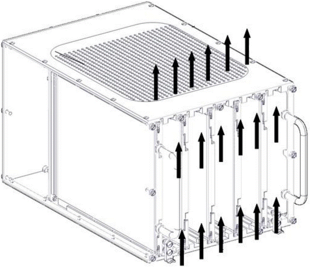
technical field [0001] The invention belongs to the forced air-cooling technology of electronic equipment, and in particular relates to a forced air-cooled chassis resistant to marine and atmospheric environments. Background technique [0002] Electronic equipment working in the marine atmospheric environment is often in an environment of high temperature, high humidity, high salt spray, and acidic atmosphere. Compared with the land environment, the corrosion rate will be greatly accelerated. [0003] The existing forced air-cooled chassis is composed of a lower cover 3, an upper cover 1, a front panel 6, a rear panel 2, a right side panel 7 and a left side panel, and the lower cover 3 and the upper cover 1 have guide rails for fixing Plate 5, lower cover 3 and upper cover 1 have cooling holes for cooling air in and out, such as figure 1 shown. [0004] The principle of equipment cooling is as follows: the cooling air enters the inside of the chassis through the ventilatio...

Claims


Application Information

Patent Timeline
Patent Type & Authority Applications(China)
IPC IPC(8): H05K7/20
CPCH05K7/20145
Inventor 陈学永刘宁吕云朋李雪冬陈建超胡培根杨成博
Owner CHINA AVIATION OPTICAL-ELECTRICAL TECH CO LTD
Learn More