Liquid crystal display device

A technology of a liquid crystal display device and a liquid crystal composition, which is applied in the direction of liquid crystal materials, instruments, chemical instruments and methods, etc., can solve problems such as white spot and uneven orientation, and achieve the effect of preventing white spot and preventing reduction

Active Publication Date: 2018-05-25
View PDF8 Cites 0 Cited by
  • Summary
  • Abstract
  • Description
  • Claims
  • Application Information

AI Technical Summary

Problems solved by technology

[0016] The present invention provides a liquid crystal display device, which prevents a decrease in voltage retention (VHR) and an increase in ion density (ID) of a liquid crystal layer by using a color filter using a specific liquid crystal composition and a specific pigment, and solves problems such as white spots and alignment problems. Poor display problems such as unevenness and screen burn-in

Method used


Image

  • Liquid crystal display device
  • Liquid crystal display device
  • Liquid crystal display device

Examples


Embodiment 1~5

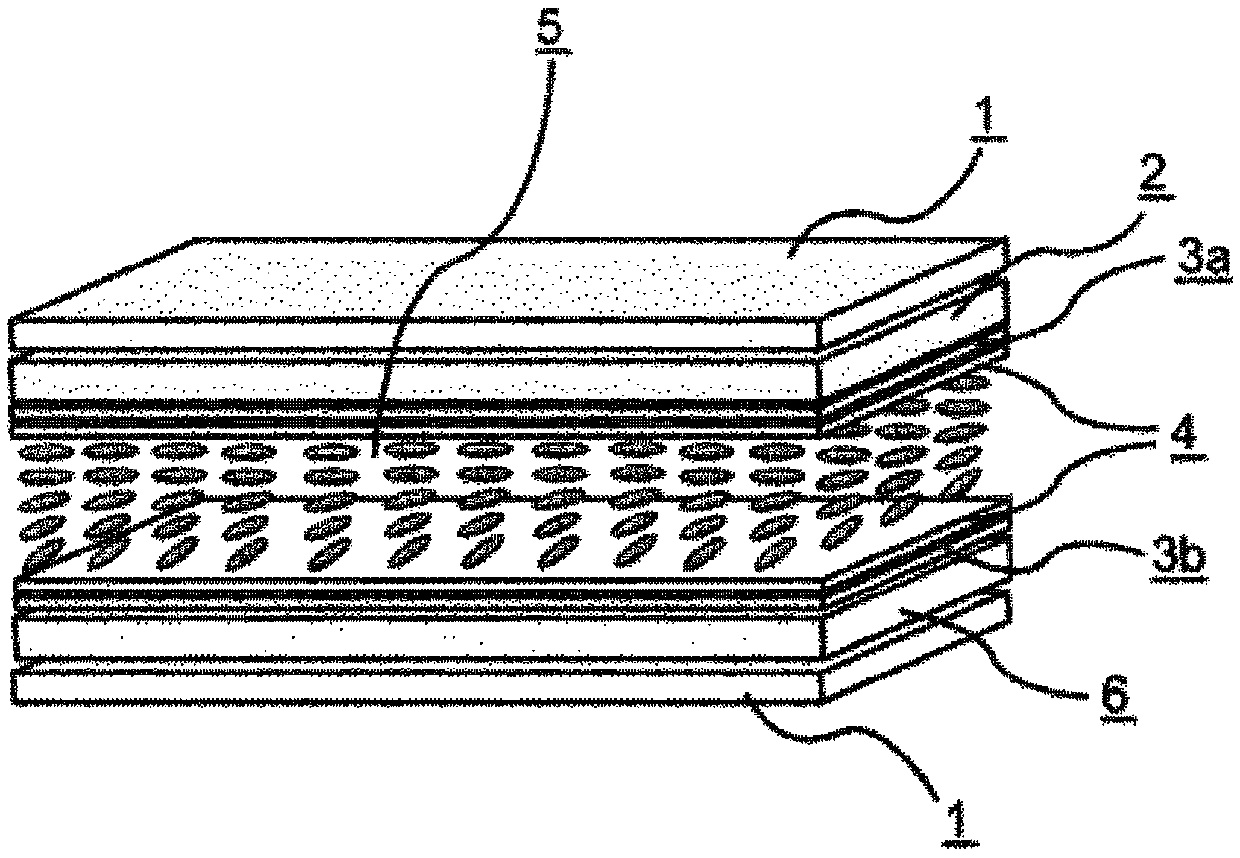
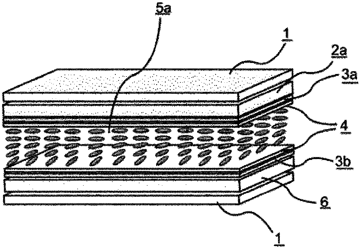
[0410] Make an electrode structure on at least one of the first and second substrates, form a horizontally oriented alignment film on the respective opposite sides, and then perform a weak rubbing treatment to make an IPS unit. Liquid crystal composition 1 shown below was sandwiched between them. The physical property values ​​of the liquid crystal composition 1 are shown in the following table. Next, using the color filters 1 to 5 shown in the table above, the liquid crystal display devices of Examples 1 to 5 were produced (d gap =4.0 μm, alignment film AL-1051). The VHR and ID of the obtained liquid crystal display device were measured. Moreover, the burn-in evaluation of the obtained liquid crystal display device was performed. The results are shown in the following tables.

[0411] [Table 4]

[0412] Liquid crystal composition 1

[0413]

[0414] [table 5]

[0415]

Example 1

Example 2

Example 3

Example 4

Example 5

liquid crysta...

Embodiment 6~15

[0419] In the same manner as in Example 1, the liquid crystal display devices of Examples 6 to 15 were prepared using the color filters 1 to 5 shown in the above table with liquid crystal compositions 2 to 3 shown in the following table interposed, and the VHR thereof was measured. and ID. Moreover, the burn-in evaluation of this liquid crystal display device was performed. The results are shown in the following tables.

[0420] [Table 6]

[0421]

[0422] [Table 7]

[0423]

[0424] [Table 8]

[0425]

[0426] The liquid crystal display devices of Examples 6 to 15 realized high VHR and small ID. Also, in the burn-in evaluation, there was no image sticking, or even if there was, it was at an extremely small and allowable level.

Embodiment 16~30

[0428] In the same manner as in Example 1, liquid crystal display devices of Examples 16 to 30 were prepared using the color filters 1 to 5 shown in the above table by interposing liquid crystal compositions 4 to 6 shown in the following table, and their VHRs were measured. and ID. Moreover, the burn-in evaluation of this liquid crystal display device was performed. The results are shown in the following tables.

[0429] [Table 9]

[0430]

[0431] [Table 10]

[0432]

[0433] [Table 11]

[0434]

[0435] [Table 12]

[0436]

[0437] The liquid crystal display devices of Examples 16 to 30 realized high VHR and small ID. Also, in the burn-in evaluation, there was no image sticking, or even if there was, it was at an extremely small and allowable level.


PUM

PropertyMeasurementUnit
particle diameteraaaaaaaaaa

Abstract

The present invention relates to a liquid crystal display device employing a colour filter in which a specific liquid crystal composition, a specific pigment, and a specific compound are used. The present invention provides a liquid crystal display device which inhibits a reduction in the voltage holding ratio (VHR) of a liquid crystal layer, inhibits an increase in ion density (ID), and resolves problems related to display defects such as white spots, alignment unevenness, and burn-in. This liquid crystal display device is characterized in that a reduction in the voltage holding ratio (VHR) of the liquid crystal layer is inhibited, an increase in ion density (ID) is inhibited, and the occurrence of display defects such as burn-in is suppressed. Accordingly, the liquid crystal display device is particularly useful as an active-matrix-drive TN-mode, IPS-mode, polymer-stabilized IPS-mode, FFS-mode, OCB-mode, VA-mode, or ECB-mode liquid crystal display device. Furthermore, the liquid crystal display device is applicable as a liquid crystal display device such as a liquid-crystal TV, monitor, portable telephone, or smartphone.

Description

technical field [0001] The present invention relates to a liquid crystal display device. Background technique [0002] Liquid crystal display devices have been used in clocks and calculators, and have been used in various household electrical equipment, measuring equipment, automotive panels, word processors, electronic notebooks, printers, computers, televisions, and the like. Representative examples of liquid crystal display methods include TN (twisted nematic) type, STN (super twisted nematic) type, DS (dynamic light scattering) type, GH (guest-host) type, IPS (in-plane switching) type, and OCB type. (Optically Compensated Birefringence) type, ECB (Voltage Controlled Birefringence) type, VA (Vertical Alignment) type, CSH (Color Super Hook) type, or FLC (Ferroelectric Liquid Crystal) and the like. In addition, as the driving method, it has also changed from the conventional static driving to the usual multiplexing driving. The simple matrix method and the active matrix (A...

Claims


Application Information

Patent Timeline
Patent Type & Authority Patents(China)
IPC IPC(8): G02F1/1335C09K19/12C09K19/20C09K19/30C09K19/42G02B5/20G02F1/13G02F1/1337
CPCC09K19/12C09K19/20C09K19/30C09K19/42G02B5/20G02F1/13G02F1/1335G02F1/1337
Inventor 栗山毅河村丞治近藤仁牧博志小池淳一郎宍仓正视
Why Eureka
Try Eureka