
Rotary electric machine stator fitted with optimized coil

A technology for rotating electrical machines and stators, which is applied in the manufacture of motor generators, prefabricated windings embedded in motors, electrical components, etc. It can solve problems such as inability to allow and no time to allow stator sintering flux to melt, so as to ensure continuity, optimize manufacturing time, The effect of shortening the time

Active Publication Date: 2017-03-22
SKYAZUR
View PDF14 Cites 15 Cited by
  • Summary
  • Abstract
  • Description
  • Claims
  • Application Information

AI Technical Summary

Problems solved by technology

This does not allow clamping mechanisms on each side of the monolithic body to temporarily hold exposed surfaces that are in contact after first being tinned with flux, nor does it allow time for sintering of the stator and melting of the flux

Method used


Image

  • Rotary electric machine stator fitted with optimized coil
  • Rotary electric machine stator fitted with optimized coil
  • Rotary electric machine stator fitted with optimized coil

Examples


Embodiment Construction

[0062] In the following description, the same reference numerals are used to identify a part of the stator object of the invention and / or the same elements on the different variants.

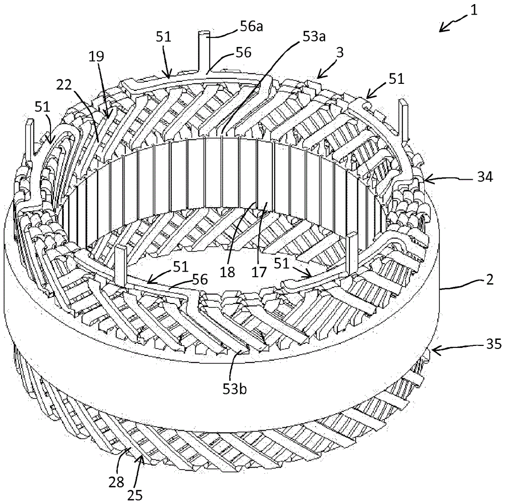
[0063] figure 1 A stator 1 of a rotating electrical machine (not shown) comprising a motor or generator is shown in . In one application, the stator 1 is intended to implement a generator or generator-starter of a motor vehicle.

[0064] This stator 1 includes a body 2 and a coil 3 . here figure 1 , the coil 3 comprises five phases 4, 5, 6, 7, 8, each phase consists of a single winding on six layers 9, 10, 11, 12, 13, 14, which in Figure 6A and Figure 6B shown in more detail. Of course, the number of phases may vary; for example three phase coils may be provided, each phase comprising a single winding. It is also possible to vary the number of windings per phase; for example two windings per phase could be provided. It is also possible to vary the number of layers per winding.

[0065]...


PUM


Abstract

The invention relates to a rotary electric machine stator (1) comprising a body (2) with slots (15), a coil (3) made of windings (4, 5, 6, 7, 8) which comprise first conductive segments (19) equipped with two first branches and second conductive segments (25) equipped with two second branches. Each conductive segment is coated with insulation except for the presence of a bared surface on each of the branches. The shapes of the bared surfaces complement one another. The first and second conducting segments are arranged in a staggered configuration and in opposite directions successively one after the other, each slot accepting first branches and second branches positioned opposite with the bared surfaces thereof respectively in contact with one another to form a continuous wire. The stator comprises means for keeping the bared surfaces in contact with one another in the slots.

Description

technical field [0001] The invention relates to a stator of a rotating electrical machine that can be used as a motor or as a generator. A particular application concerns generators in the motor vehicle sector. Other applications are also foreseen, such as generators in the wind power sector. The main objective of the invention is to optimize the output power of the machine and its manufacturing cost. Background technique [0002] It is known that a stator comprises a body, also referred to as a core, which comprises a plurality of steel plates and which comprises slots. The slot has, for example, a longitudinal shape parallel to the axis of the body which coincides with the axis of rotation of the rotor of the rotating electrical machine. The slots extend radially around the body in a circumferential manner and are spaced apart from each other by teeth. These teeth may each comprise at its radial end a dedendum extending in a circumferential manner on each side of said ...

Claims


Application Information

Patent Timeline
IPC IPC(8): H02K3/12H02K3/28H02K15/06
CPCH02K3/12H02K3/28H02K15/064H02K15/0068H02K15/085
Inventor N.兰拉德
Owner SKYAZUR
Features
  • Generate Ideas
  • Intellectual Property
  • Life Sciences
  • Materials
  • Tech Scout
  • Unparalleled Data Quality
  • Higher Quality Content
  • 60% Fewer Hallucinations
Learn More