
Welding platform used for welding photovoltaic equipment multifunctional cart frame

A technology of photovoltaic equipment and welding platform, which is applied in the direction of welding equipment, auxiliary welding equipment, welding/cutting auxiliary equipment, etc., and can solve the problem of affecting the transportation efficiency and transportation safety, the low flatness of the multifunctional cart frame, and the large welding workload and other issues, to achieve the effect of improving conveying efficiency and conveying safety, good welding effect and low production cost

Inactive Publication Date: 2017-03-29
48TH RES INST OF CHINA ELECTRONICS TECH GROUP CORP
View PDF16 Cites 13 Cited by
  • Summary
  • Abstract
  • Description
  • Claims
  • Application Information

AI Technical Summary

Problems solved by technology

[0004] (1) Welding is easy to deform
In the metal welding work of the multi-functional cart frame in the prior art, the object to be welded will generate relatively large thermal stress during welding, and this thermal strain will generate shrinkage stress when the weld bead cools, thus causing the weldment to bend and twist Or torsion and other phenomena, resulting in large welding deformation
This makes the flatness of the frame of the multifunctional trolley low, which seriously affects the subsequent conveying efficiency and conveying safety.
[0005] (2) Low welding efficiency
This makes the operator have to adjust the welding fixing method of different specifications and sizes under the premise of ensuring the welding quality, resulting in a large welding workload and extremely low welding efficiency

Method used


Image

  • Welding platform used for welding photovoltaic equipment multifunctional cart frame
  • Welding platform used for welding photovoltaic equipment multifunctional cart frame
  • Welding platform used for welding photovoltaic equipment multifunctional cart frame

Examples


Embodiment Construction

[0028] The present invention will be described in further detail below in conjunction with specific embodiments and accompanying drawings.

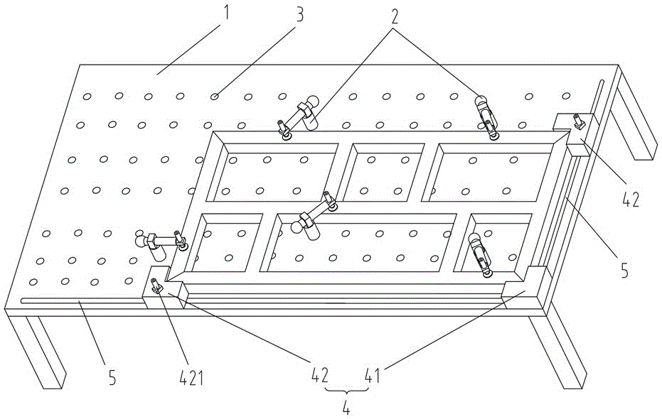
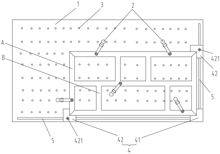
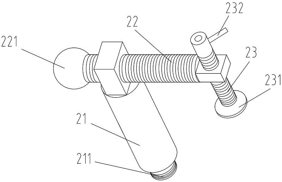
[0029] Such as Figure 1 to Figure 3 As shown, the present invention provides a welding platform for welding the multifunctional cart frame of photovoltaic equipment, including a platform 1 for placing parts to be welded, the platform 1 is flat, and the platform 1 is provided with a plurality of detachable For the vertical compression device 2 for compressing the parts to be welded, each vertical compression device 2 includes a fixed rod 21, a horizontal adjustment rod 22 and a longitudinal adjustment rod 23, the lower end of the fixed rod 21 is used to be fixed on the platform 1, and the horizontal The adjustment rod 22 is horizontally installed on the upper end of the fixed rod 21, and one end of the horizontal adjustment rod 22 is pierced with a vertically arranged longitudinal adjustment rod 23, and the longitudinal adjustment rod 23 ...


PUM


Abstract

The invention discloses a welding platform used for welding a photovoltaic equipment multifunctional cart frame. The welding platform comprises a platform body used for holding a to-be-welded part. The platform body is provided with a plurality of detachable vertical pressing devices used for pressing the to-be-welded part. Each vertical pressing device comprises a fixing rod, a transverse adjusting rod and a longitudinal adjusting rod. The lower end of the fixing rod is used for being fixed to the platform body. The transverse adjusting rod is horizontally mounted at the upper end of the fixing rod. One end of the transverse adjusting rod is provided with the longitudinal adjusting rod in a penetrated mode. The longitudinal adjusting rod and the transverse adjusting rod are in threaded connection and used for rotatably adjusting the horizontal height of the longitudinal adjusting rod, so that the longitudinal adjusting rod presses and fixes the to-be-welded part to the platform body, and then welding operation is conducted. The welding platform has the advantages of being reasonable in structure design, low in manufacturing cost, convenient and rapid to operate, small in welding deformation and capable of improving working efficiency.

Description

technical field [0001] The invention mainly relates to the field of photovoltaic equipment, in particular to a welding platform for welding the frame of a multifunctional trolley for photovoltaic equipment. Background technique [0002] In the field of photovoltaic equipment, a multifunctional cart is used, and the multifunctional cart is used to transport photovoltaic equipment such as multiple graphite boats. In actual work, the flatness of the frame of the photovoltaic equipment multi-function cart is extremely high, because if there is a slight unevenness, it is very likely that the graphite boat on the multi-function cart will fall during the subsequent transportation process, and even cause serious damage. The whole slipped and broke, which greatly affected the conveying efficiency and conveying safety, and caused serious production and operation problems. [0003] The frame of the current photovoltaic equipment multifunctional cart is made by welding multiple metal s...

Claims


Application Information

Patent Timeline
Patent Type & Authority Applications(China)
IPC IPC(8): B23K37/04
CPCB23K37/0461
Inventor 卓勇军舒勇东刘洪文彭志虹谢辉
Owner 48TH RES INST OF CHINA ELECTRONICS TECH GROUP CORP
Learn More