A cleaning device for a compaction apparatus

A technology for cleaning devices and equipment, which can be used in drafting equipment, textiles and papermaking, spinning machines, etc., and can solve problems such as adverse effects on the compaction quality of fiber materials.

Active Publication Date: 2017-03-29
MASCHINENFABRIK RIETER AG
View PDF7 Cites 1 Cited by
  • Summary
  • Abstract
  • Description
  • Claims
  • Application Information

AI Technical Summary

Problems solved by technology

As a result, the speed ratio between the compacting elements and the lower output rollers of the drawing frame is variable, which has a negative effect on the compaction quality of the fiber material

Method used


Image

  • A cleaning device for a compaction apparatus
  • A cleaning device for a compaction apparatus
  • A cleaning device for a compaction apparatus

Examples


Embodiment Construction

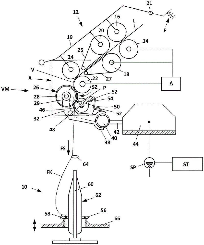
[0021] figure 1 Shown is a schematic side view of a spinneret 10 of a spinning machine (ring spinning machine) having a drawing frame unit 12 provided with a pair of feed rollers 14, 16. Center roller pairs 18, 20 and output roller pairs 22, 24. The bottom roller pairs 14, 18, 22 are connected to a drive A, which is schematically shown in the figures. The upper roller pair 16 , 20 , 24 is designed as a pressure roller and is mounted such that it can be moved rotationally on a pivotally mounted pressure arm 19 . The pressure arm 19 is mounted to pivot about a lever shaft 21 and is acted upon by a spring element F. As shown in FIG. The pressure rollers 16 , 20 , 24 and / or the belt 27 are driven by friction via the belt 25 running on the driven bottom rollers 14 , 18 , 22 . The peripheral speed of the driven roller 18 is slightly greater than the peripheral speed of the driven roller 14 .

[0022] The fiber material fed to the drawing frame unit 12 is subjected to predrawing ...


PUM


Abstract

The invention relates to a cleaning device for a compression device with a drive element (70) and a fiber processing element (26) which is rotatably mounted about an axis of rotation and has a projection (72). The projection (72) cooperates with the drive element (70) and forms a gear stage (G2). The gear stage (G2) is designed in such a way that the fiber processing element (26) and the drive element (70) rotate at a different rotational speed. According to the invention, the cleaning device comprises a cleaning element (76) which is arranged in the direction of the axis of rotation on an end face (82) of the drive element (70) facing away from the fiber processing element (26) and is non-rotatably connected to the projection (72). Furthermore, the cleaning element 76 has at least one stripping edge 78, which extends in a plane (88) parallel to the end face (82) of the drive element (70) and has an increasing distance from the axis of rotation.

Description

technical field [0001] The invention relates to a cleaning device for a compacting plant, said cleaning device comprising a drive element and a fiber handling element mounted to rotate about an axis of rotation and having a shaped part, wherein the shaped part is aligned with the The drive element cooperates and forms a gear stage designed such that the shaped part and the drive element rotate at different rotational speeds. Background technique [0002] WO 2012068692 A1 describes a device for compacting a fiber sliver on a spinning machine, which has a driven and rotating compacting element, which is acted upon by intake air and has a shaped The forming part cooperates with the driving element so as to form a driving connection with the driven element of the spinning machine in the operating position and form a gear stage. [0003] One disadvantage of the device according to WO 2012068692 A1 is that during the compaction operation individual fibers loosen from the fiber ma...

Claims


Application Information

Patent Timeline
Patent Type & Authority Applications(China)
IPC IPC(8): D01H11/00
CPCD01H11/00D01H5/72
Inventor L.马里纳
Owner MASCHINENFABRIK RIETER AG
Why Eureka
Try Eureka