
Engine starting and stopping running control method

A control method and stop operation technology, applied in the direction of engine control, machine/engine, mechanical equipment, etc., can solve the problems of high cost of control devices, difficult to achieve angle positioning, etc.

Active Publication Date: 2017-03-29
SANYANG IND CO LTD
View PDF7 Cites 4 Cited by
  • Summary
  • Abstract
  • Description
  • Claims
  • Application Information

AI Technical Summary

Problems solved by technology

[0004] The method of starting the engine of the above-mentioned existing starting and generating device has a disadvantage. Before each start, the crankshaft must be accurately reversed to a specific predetermined position, and the inertia must be added after the rotation to generate enough torque to overcome the compression point. , so that the engine starts smoothly
It is difficult to achieve accurate specific crankshaft angle positioning in control, and the cost of the required control device is relatively high

Method used

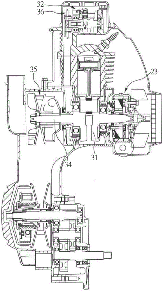
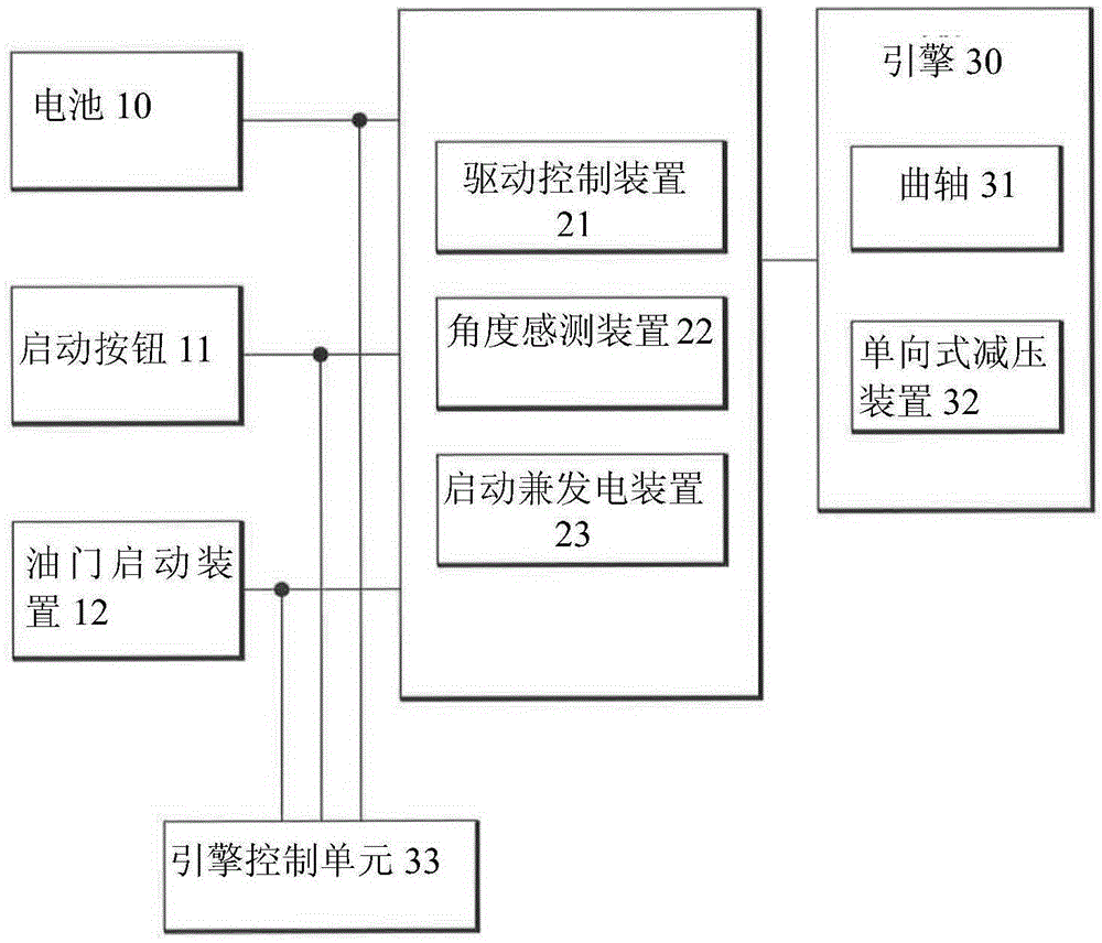

Image

  • Engine starting and stopping running control method
  • Engine starting and stopping running control method
  • Engine starting and stopping running control method

Examples


Embodiment Construction

[0060] In order to make it easier for those skilled in the art to understand and realize the present invention, the embodiments of the present invention are described in conjunction with the accompanying drawings.

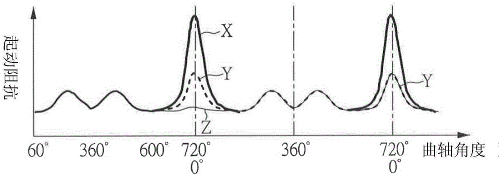
[0061] The so-called engine decompression device is generally used to leak part of the gas pressure during the compression stroke of the engine piston to reduce the engine resistance. Please refer to figure 1 The comparison chart of the crankshaft angle position and the starting impedance of the starting and generating device. As shown in the figure, the coordinates on the vertical axis represent the starting resistance of the forward rotation of the starting and generating device, and the coordinates on the horizontal axis represent the rotation angle of the crankshaft. This embodiment adopts the working principle of a four-stroke engine, which is distinguished according to the position of the piston in the cylinder. Therefore, it reaches the top dead center (T.D....


PUM


Abstract

The invention relates to an engine starting and stopping running control method. A starting control method comprises the steps that A, whether an engine starting signal is received or not is judged; B, a bent axle is driven to reversely rotate within a certain angle range, and a pressure reduction device is made to act; C, the bent axle is driven to forwards rotate, an engine is made to be started, whether the rotation speed of the bent axle is larger than the engine starting threshold rotation speed or not is judged, if the rotation speed of the bent axle is larger than the engine starting threshold rotation speed, the step D is executed, if the rotation speed of the bent axle is not larger than the engine starting threshold rotation speed, the step C is executed, whether the time of driving exceeds the preset time or not is judged, if the time of driving exceeds the preset time, driving is stopped, the step A is executed, and if the time of driving does not exceed the preset time, the step C is executed; and D, driving is stopped, and a power generation mode is executed. A stopping running control method comprises the steps that A, the angle of the bent axle is detected before the engine stops running, and whether the spontaneous reverse rotation action exists or not is judged, wherein if the spontaneous reverse rotation action exists, the step B is executed, and if the spontaneous reverse rotation action does not exist, the step C is executed; B, the spontaneous reverse rotation action is controlled, the bent axle reversely rotates within a certain angle range, and control is stopped after the pressure reduction device acts; and C, the bent axle is driven to forwards rotate within a certain angle range, then the bent axle is driven to reversely rotate within a certain angle range, and control is stopped after the pressure reduction device acts.

Description

technical field [0001] The invention relates to a control method for starting and stopping an engine, in particular to a control method for starting and stopping an engine suitable for locomotives. Background technique [0002] At present, there is an integrated starter and generator (Integrated Starter and Generator, hereinafter referred to as ISG) in the market to increase the energy saving effect of the locomotive, and it has the function of idling stop and restart. Generally, when a locomotive is turned off, the stroke will stop before the compression top dead center. At this time, the ISG needs a large torque to overcome the compression pressure of the engine and start the engine. [0003] The existing method of starting the engine is to reverse the crankshaft to a specific predetermined position before starting the engine, and then make it start to rotate forward to drive the engine to have a greater inertia, thereby overcoming the torsional resistance of the compressi...

Claims


Application Information

Patent Timeline
IPC IPC(8): F02D11/10
Inventor 宁攸威邱景崇曾威婷潘冠佑尤志文
Owner SANYANG IND CO LTD
Learn More