A Centrifugal Mechanism for Automatic Shifting
A centrifugal mechanism and automatic shifting technology, applied in automatic clutches, clutches, mechanical equipment, etc., can solve problems such as poor stability and complex structure, and achieve the effect of high stability, good stability and improved centrifugal force.
- Summary
- Abstract
- Description
- Claims
- Application Information
AI Technical Summary
Problems solved by technology
Method used
Image
Examples
Embodiment 1
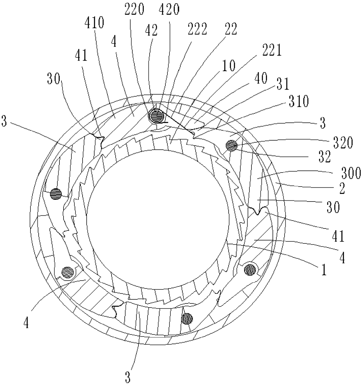
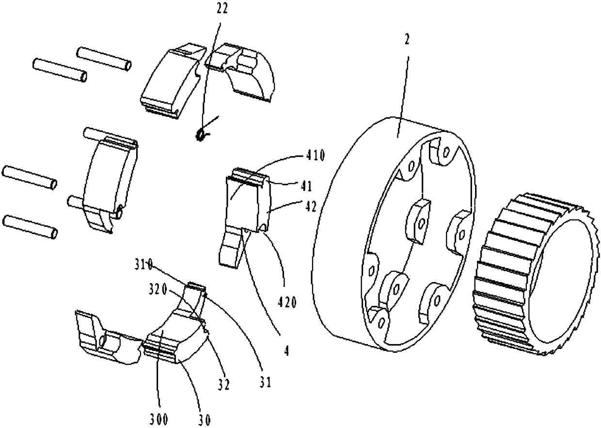
[0030] Participate Figure 1 to Figure 3 As shown, the present invention discloses a centrifugal mechanism for automatic shifting, which is mainly composed of a ratchet wheel 1, a pawl fixing frame 2, three pawl members 3, and three linkage members 4, of which three pawls The member 3 and the three linkage members 4 are arranged between the ratchet wheel 1 and the pawl fixing frame 2, and are arranged at intervals in the circumferential direction, that is, a linkage member 4 is set between every two adjacent pawl members 3.
[0031] The ratchet wheel 1 is located in the pawl fixing frame 2, and the ratchet wheel 1 is provided with evenly arranged ratchet teeth 10 on its outer circumference.
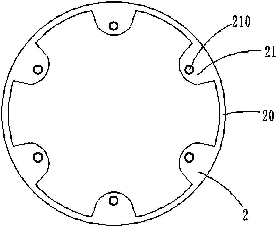
[0032] The pawl fixing frame 2 includes an annular base 20 and a plurality of mounting seats 21 extending inward from the inner wall of the annular base 20. The mounting seats 21 are provided with pin holes 210 for mounting pins.
[0033] The pawl member 3 includes a first end portion 30, a sec...
Embodiment 2
[0038] Participate Figure 4 As shown, the structure of the centrifugal mechanism in this embodiment is the same as that of Embodiment 1, the difference is that in Embodiment 1, the first end 30 of the pawl member 3 in the radial direction is limited to the fourth end In the inner side of the portion 41, the second end 31 of the pawl 3 in the radial direction is confined to the inner side of the third end 40 of the linkage 4, and in this embodiment, the fourth end of the linkage in the radial direction The portion 41 is limited to the inner side of the first end 30 of the pawl member 3, and the third end 40 of the linkage member 4 is limited to the inner side of the second end 31 of the pawl member 3 in the radial direction.
[0039] The working principle of the centrifugal mechanism in this embodiment is: the working principle of the centrifugal mechanism in this embodiment is: as the speed of the pawl holder 2 increases, the counterweight 300 provided on the first end 30 of the ...
Embodiment 3
[0041] Reference Figure 5 As shown, the remaining structural principles of the centrifugal mechanism in this embodiment are the same as those of Embodiment 1, and the difference is that the centrifugal mechanism in Embodiment 1 is mainly composed of a ratchet wheel 1, a pawl holder 2, and three pawls. The piece 3 and the three linkage pieces 4 are composed of several parts, of which the three pawl pieces 3 and the three linkage pieces 4 are arranged between the ratchet wheel 1 and the pawl fixing frame 2, and are arranged at intervals in the circumferential direction, that is, each A linkage member 4 is arranged between two adjacent pawl members 3. The centrifugal mechanism in this embodiment is mainly composed of a ratchet wheel 1, a pawl fixing frame 2, a torsion spring 22, two pawl members and a linkage member 4. Among them, two pawl members 3 and a linkage member 4, a torsion spring 2 is arranged between the ratchet wheel 1 and the pawl holder 2 and arranged at intervals i...
PUM
 Abstract
Description
Claims
Application Information
 - R&D
- Intellectual Property
- Life Sciences
- Materials
- Tech Scout
- Unparalleled Data Quality
- Higher Quality Content
- 60% Fewer Hallucinations
Browse by: Latest US Patents, China's latest patents, Technical Efficacy Thesaurus, Application Domain, Technology Topic, Popular Technical Reports.
© 2025 PatSnap. All rights reserved.Legal|Privacy policy|Modern Slavery Act Transparency Statement|Sitemap|About US| Contact US: help@patsnap.com


