Probe structure and manufacturing method thereof

A manufacturing method and probe technology, applied in the direction of instruments, measuring devices, measuring electricity, etc., can solve the problem of easy overheating of probes, and achieve the effect of overheating easily

Inactive Publication Date: 2019-03-19
MPI CORP
View PDF7 Cites 0 Cited by
  • Summary
  • Abstract
  • Description
  • Claims
  • Application Information

AI Technical Summary

Problems solved by technology

[0004] In view of this, the object of the present invention is to provide a probe structure and a method for manufacturing the probe structure, which can solve the problem that the probes of the current technology are prone to overheating during testing by means of bump shunting

Method used


Image

  • Probe structure and manufacturing method thereof
  • Probe structure and manufacturing method thereof
  • Probe structure and manufacturing method thereof

Examples


Embodiment Construction

[0048] Below in conjunction with accompanying drawing, structural principle and working principle of the present invention are specifically described:

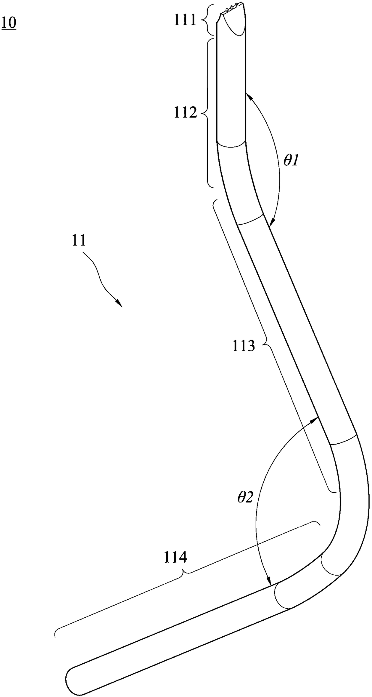
[0049] Please refer to Figure 1A , is a schematic diagram of the probe structure of the present invention. The disclosed probe structure 10 includes a probe body 11 , and the probe body 11 includes a needle tip 111 , a needle tail 112 , a first segment 113 and a second segment 114 . The needle tail 112 is directly connected to the needle tip 111 , and the two ends of the first section 113 are respectively connected to the needle tail 112 and the second section 114 . The needle tail 112 and the first section 113 define a first included angle θ1, which is in the range of 150 degrees to 175 degrees. The first segment 113 and the second segment 114 define a second included angle θ2, which is in the range of 75 degrees to 105 degrees. In this embodiment, the needle tip 111 , the needle tail 112 , the first segment 113 and the sec...


PUM


Abstract

The present invention provides a probe structure. The probe structure includes a probe body which includes a probe tip portion. The probe tip portion includes an end surface, two inclined surfaces and at least three bulges. The two inclined surfaces respectively extend away from the end surface. The at least three bulges are located at the end surface. The intersection of the end surface and each bulge is machined to have a fillet thereat. The pitch between two neighboring bulges is larger than or equal to 150 microns. In addition, the present invention also provides a manufacturing method of the probe structure.

Description

technical field [0001] The invention relates to a probe structure and a manufacturing method thereof, in particular to a probe structure used in integrated circuit testing and a manufacturing method thereof. Background technique [0002] In recent years, the application of integrated circuit (integrated circuit) has been gradually popularized. After the integrated circuit is manufactured, in order to screen out defective products, test signals are usually transmitted to the integrated circuit through a test device to test whether its function meets expectations, so as to Control the factory yield of integrated circuits. Here, the existing test technology can use the probe device to directly contact the pad or I / O pad on the integrated circuit to be tested, and send the test signal to the integrated circuit through the test device through the probe. The circuit is tested, and the test result is sent back to the test device by the probe for analysis. [0003] The probe itsel...

Claims


Application Information

Patent Timeline
Patent Type & Authority Patents(China)
IPC IPC(8): G01R1/067
CPCG01R1/06738G01R1/06755
Inventor 蔡锦溢陈建宏余陈志
Owner MPI CORP
Why Eureka
Try Eureka