
Optical cable transfer box with heat dissipation and cooling function

A technology of optical cable transfer boxes and transfer boxes, which is applied in the direction of light guides, optics, optical components, etc., can solve problems such as shortening the service life of optical cable transfer boxes, potential safety hazards for operators' network security, and poor management of optical cable transfer boxes. It is safe and convenient to use and has the effect of improving the protection ability

Inactive Publication Date: 2017-03-29
胡剑民
View PDF0 Cites 7 Cited by
  • Summary
  • Abstract
  • Description
  • Claims
  • Application Information

AI Technical Summary

Problems solved by technology

[0004] In the prior art, the optical cable transfer box is used in the urban area road or the access network, and it is inconvenient to check the situation in the optical cable transfer box. In the prior art, the optical cable transfer box generally has the problem of poor management. It can open multiple fiber optic cable transfer boxes, and even open the fiber optic cable transfer boxes of other operators. It can be easily opened with other tools, which brings great potential safety hazards to the network security of operators. Only a few manufacturers provide The optical cable transfer box has the access control function or is equipped with an electric control lock. The optical cable transfer box generates a lot of heat during the working process. If the optical cable transfer box is placed outdoors for a long time, it is easy to accumulate a large amount of moisture in the optical cable transfer box, which is not conducive to the optical cable transfer box. The work will greatly shorten the service life of the optical cable transfer box

Method used


Image

  • Optical cable transfer box with heat dissipation and cooling function
  • Optical cable transfer box with heat dissipation and cooling function

Examples


Embodiment Construction

[0017] The following will clearly and completely describe the technical solutions in the embodiments of the present invention with reference to the accompanying drawings in the embodiments of the present invention. Obviously, the described embodiments are only some, not all, embodiments of the present invention. Based on the embodiments of the present invention, all other embodiments obtained by persons of ordinary skill in the art without making creative efforts belong to the protection scope of the present invention.

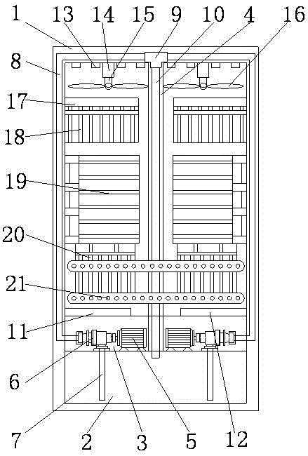
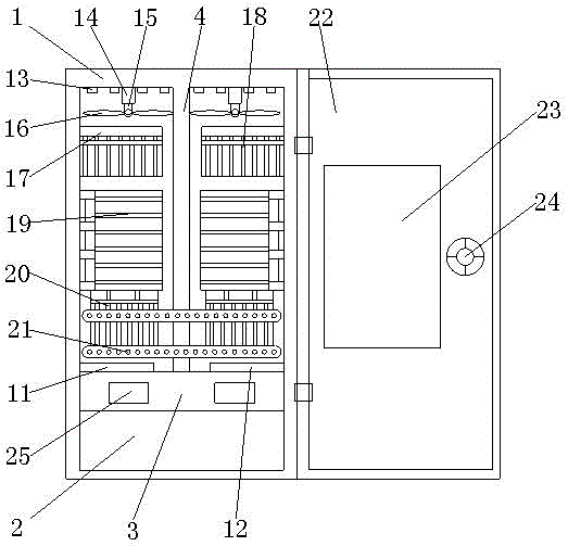
[0018] see Figure 1~2 , in an embodiment of the present invention, a fiber optic cable transfer box with heat dissipation and cooling function includes a transfer box body 1, the transfer box body 1 is a double-layer structure, and a cooling oil tank 2 is provided inside the transfer box body 1, and the cooling oil tank 2 The upper part is provided with an oil outlet hole and an oil return hole. The upper part of the cooling oil tank 2 is provided with a moto...


PUM


Abstract

The invention discloses an optical cable transfer box with a heat dissipation and cooling function. The optical cable transfer box comprises a transfer box body; a cooling oil box is arranged in the transfer box body; one inner wall of the transfer box body is provided with illumination lamp tubes and heat dissipation devices; each heat dissipation device includes a micro motor, a micro motor cavity, a fan rotation shaft and fan blades; and the inner walls of two sides of the transfer box body are provided with trunk layer optical cable mounting portions, line distribution layer optical cable mounting portions, light splitters, control panels and optical cable junction boxes. The optical cable transfer of the invention has the advantages of scientific and reasonable structure, safe and convenient use and easiness in check. According to the optical cable transfer box of the invention, the box body is of a double-layer structure, so that the protection capability of the box body can be improved; with an electronic control lock adopted, internal components of the transfer box can be prevented from being damaged or stolen; temperature and humidity in transfer box body can be monitored in real time, and double-cooling processing can be performed timely; and therefore, the safe working of the optical cable transfer box can be ensured, and the service life of the optical cable transfer box can be prolonged.

Description

technical field [0001] The invention relates to an optical cable transfer box, in particular to an optical cable transfer box with the function of heat dissipation and cooling. Background technique [0002] The optical cable transfer box is a transfer device that provides optical cable termination and jumper connection for the backbone layer optical cable and the distribution layer optical cable. After the optical cable is introduced into the optical cable transfer box, after being fixed, terminated, and distributed, the backbone layer optical cable and the distribution layer optical cable are connected using a jumper fiber. [0003] The capacity of the optical cable transfer box refers to the maximum number of fiber cores that can be terminated in the optical cable transfer box. The size of the capacity is directly proportional to the volume of the box, the overall cost, and the difficulty of construction and maintenance, so it should not be too large. In actual design an...

Claims


Application Information

Patent Timeline
IPC IPC(8): G02B6/44
CPCG02B6/4441G02B6/4446G02B6/446
Inventor 胡剑民
Owner 胡剑民
Features
  • Generate Ideas
  • Intellectual Property
  • Life Sciences
  • Materials
  • Tech Scout
  • Unparalleled Data Quality
  • Higher Quality Content
  • 60% Fewer Hallucinations
Learn More