
Three-dimensional print slicing method based on T-spline surface

A spline surface and three-dimensional printing technology, which is applied in special data processing applications, instruments, electrical digital data processing, etc., can solve problems such as difficult slicing and poor promotion

Active Publication Date: 2017-03-29
ZHEJIANG UNIV
View PDF6 Cites 24 Cited by
  • Summary
  • Abstract
  • Description
  • Claims
  • Application Information

AI Technical Summary

Problems solved by technology

[0008] In order to solve the problem of poor generalization of the existing CAD direct slicing technology and the difficulty of slicing caused by the inherent defects of STL, the present invention provides a 3D printing slicing method based on T-spline surface

Method used


Image

  • Three-dimensional print slicing method based on T-spline surface
  • Three-dimensional print slicing method based on T-spline surface
  • Three-dimensional print slicing method based on T-spline surface

Examples


Embodiment 1

[0132] Select a T-spline model with a free-form surface, such as Image 6 shown. The special feature of the surface is that it has a complex free-form surface appearance, but due to the advantages of the T-spline modeling theory, the complex model surface is expressed with only a few control vertices. The T-spline model is expressed by TSM file, the file size is 29KB; the model is expressed by STL file, the file size is 5072KB. The slice layer thickness is set to 0.1mm, and the data allowable error is 0.001mm.

[0133] Figure 7 The slicing results and local amplification effects of the T-spline surface of Example 1 are shown, and it can be clearly seen that the T-spline surface realizes layered slicing according to the set layer thickness, which illustrates the effectiveness and accuracy of the method of the present invention. sex.

Embodiment 2

[0135] The selected T-spline surface to be sliced ​​is as Figure 8 shown. The special feature of this curved surface is that there are multiple slicing contour rings at the same height, and the multi-region contour slicing method in step 105 is used to realize slicing. The T-spline model is expressed by TSM file, the file size is 3KB; the model is expressed by STL, the file size is 2816KB. In order to clearly show the slice effect, this example chooses 1.0mm slice layer thickness, and the data allowable error is 0.001mm.

[0136] Figure 9 shows the effect of multi-region T-spline surface slicing, Figure 10 is the left view of the slice profile, Figure 11 A top view of the slice profile. It can be clearly seen that the multi-region slicing method for T-spline curved surfaces proposed by the present invention can effectively realize the recognition and slicing functions of multi-contours of T-spline curved surfaces at the same height, which illustrates the advantages of...


PUM


Abstract

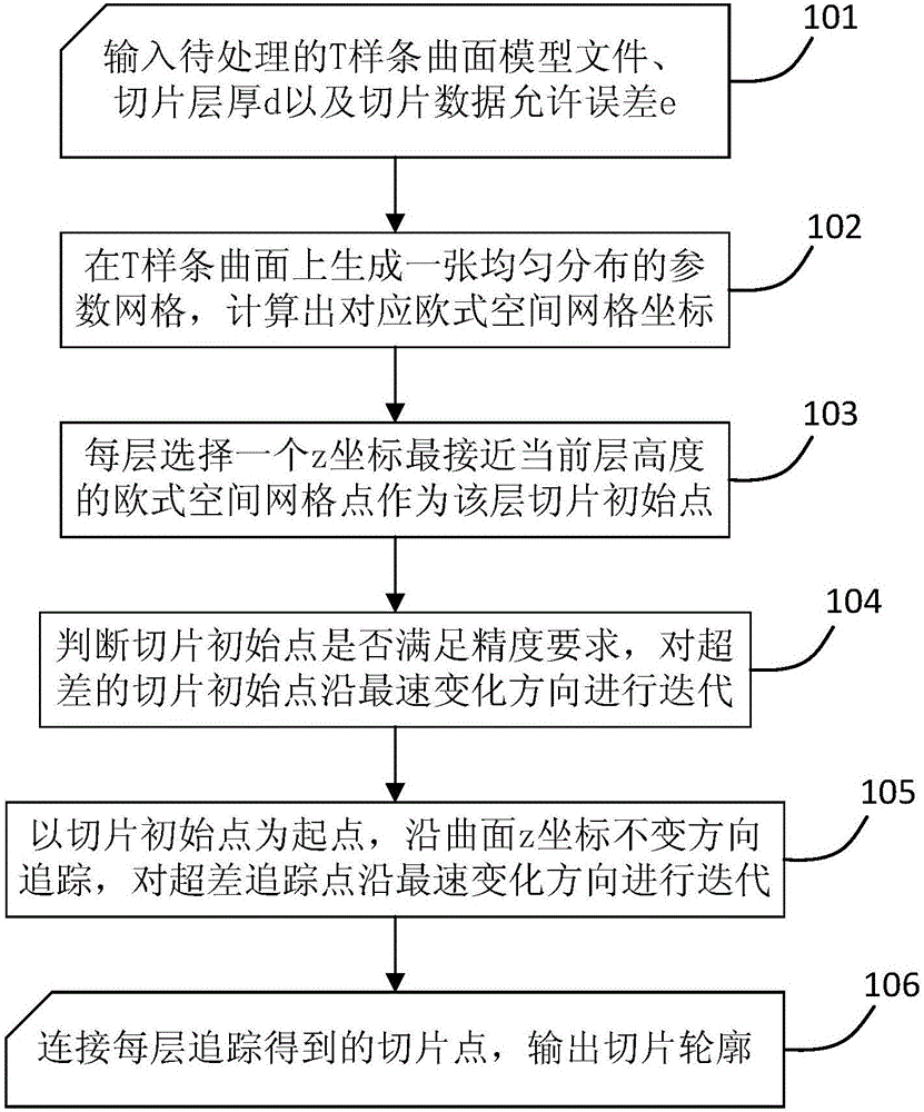
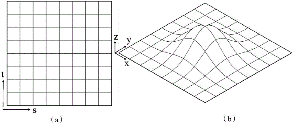
The present invention discloses a three-dimensional print slicing method based on a T-spline surface. The method comprises: inputting a to-be-processed T-spline surface, a slice layer thickness and a slice data allowable error; in a T-spline surface parameter field, generating a uniformly distributed parameter grid, and calculating a corresponding Euclidean space grid; according to a model layer thickness, selecting a grid point whose z coordinate is closest to a current layer as a slide initial point at each layer; iterating the slide initial point that exceeds the error along a steepest change direction; by using the slide initial point of each layer as a start point, tracking along an unchanged direction of the z coordinate of the surface, and iterating a slide point that exceeds the error along the steepest change direction, and finally obtaining all slice points that satisfy a precision requirement; and connecting the slice points of each layer, and outputting a slice contour. According to the method provided by the present invention, slicing of the T-spline surface is realized by using a numerical method, and the defects of huge data volume and low precision of traditional three-dimensional printing are solved, so that the method is particularly applicable for three-dimensional print slice processing of models with a complex free surface appearance or internal holes.

Description

technical field [0001] The invention belongs to the technical field of three-dimensional printing computer aided manufacturing (Computer aided manufacturing, CAM), and in particular relates to a three-dimensional printing slicing method based on a T-spline surface. Background technique [0002] 3D printing is an additive manufacturing technique that originated in the 1980s. Although dozens of printing processes for different materials have been developed, the basic principle of printing is to accumulate materials layer by layer and finally manufacture the required parts. Based on this principle, 3D printing can easily solve the manufacturing problems of complex shapes, and provide new processing solutions for parts that are inconvenient to be processed by traditional subtractive manufacturing. 3D printing mainly includes three basic steps: the user first needs to design the shape of the part in the CAD software; then import the 3D model into the 3D printing CAM software sys...

Claims


Application Information

Patent Timeline
Patent Type & Authority Applications(China)
IPC IPC(8): G06F17/50
CPCG06F30/20
Inventor 傅建中冯嘉炜林志伟商策
Owner ZHEJIANG UNIV
Learn More