Sliding nozzle

A sliding type, nozzle technology, applied in the direction of engine components, combustion engines, machines/engines, etc., can solve the problems of scrapped nozzle ring components, low assembly accuracy, large positioning errors, etc., to eliminate material deformation and process accuracy loss, improve Effects of transmission accuracy and wear resistance, quantity reduction and fit accuracy

Inactive Publication Date: 2014-01-22
汉美综合科技(常州)有限公司
View PDF7 Cites 9 Cited by
  • Summary
  • Abstract
  • Description
  • Claims
  • Application Information

AI Technical Summary

Problems solved by technology

[0006] The disadvantages of this mechanism are: 1) The friction pair between the rocker arm and the synchronous ring is line-surface contact, frequent movement will easily lead to wear of the U-shaped slot of the synchronous ring
Tests have shown that only 50 hours of continuous operation will increase the width of the card slot by 0.2-0.4mm, which is equivalent to turning the guide vane by 1°-2°, which will not only reduce the control accuracy, but also easily cause adjacent flow guides The direct distance between the blades becomes smaller, which leads to adhesion under high temperature conditions, which eventually leads to serious failure of the supercharger, which will greatly reduce the effective life of the product; 2) The guide vanes and rocker arms are welded together, this The assembly accuracy of the welding process is low, and it is easy to cause welding deformation, and once the welding fails, the entire nozzle ring assembly will be scrapped, and the production cost is high; 3) The synchronization ring is positioned by three positioning sleeves, and the positioning error is large. Further reduce the overall control accuracy of the mechanism

Method used


Image

  • Sliding nozzle
  • Sliding nozzle
  • Sliding nozzle

Examples


Embodiment Construction

[0030] The following will clearly and completely describe the technical solutions in the embodiments of the present invention. Obviously, the described embodiments are only some of the embodiments of the present invention, rather than all the embodiments. Based on the embodiments of the present invention, all other embodiments obtained by persons of ordinary skill in the art without making creative efforts belong to the protection scope of the present invention.

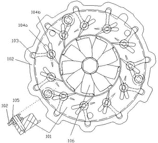
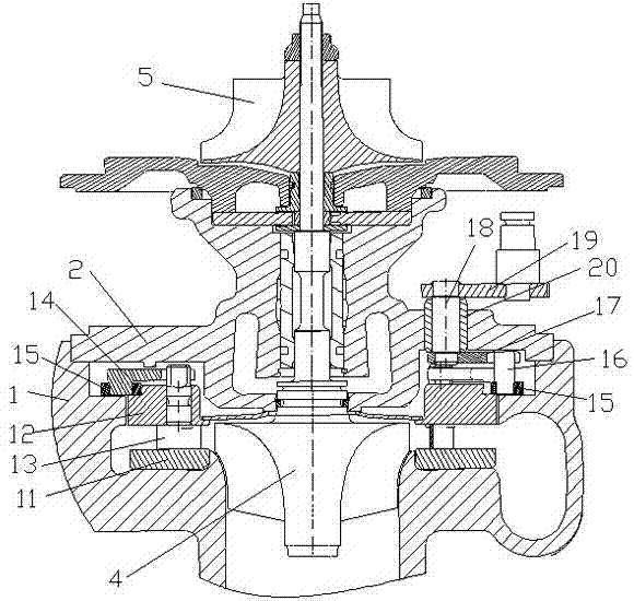
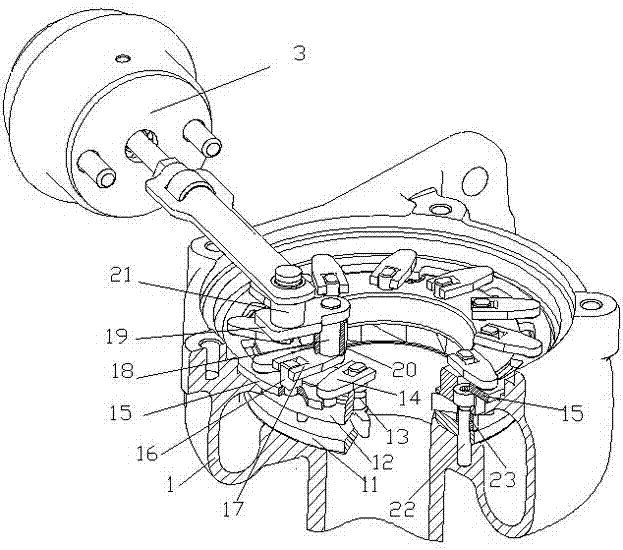
[0031] see Figure 2-Figure 6 , the embodiment of the present invention includes:

[0032] A sliding nozzle, comprising: an upper nozzle ring 12 and a lower nozzle ring 11 fixed on the volute by screws 22, a rotatable synchronous ring 15 is coaxially arranged on the upper nozzle ring 12, and the synchronous ring 15 It is arranged on a step of the upper nozzle ring 12, and the upper nozzle ring 12 can rotate around the step surface, and can drive two slider devices to move.

[0033] The present invention utilizes th...


PUM


Abstract

The invention discloses a sliding nozzle. A rotatable synchronous ring is arranged on an upper nozzle ring in a coaxial mode, and a synchronous ring inner circle connected with the upper nozzle ring in an assembling mode is of an interrupted structure in the radial direction. A first sliding block device comprises a flow guiding vane and an open shifting fork connected with the shaft end of the flow guiding vane. The shaft end of the flow guiding vane is provided with two parallel lateral planes. One end of the open shifting fork is connected with the two lateral planes in a matched mode. A second sliding block device comprises a main shifting fork assembly, one end of the main shifting fork assembly is connected with an actuator, and the other end of the main shifting fork assembly is connected with the synchronous ring through a synchronous pin. By means of the sliding nozzle, precision loss caused by fast abrasion of a line-plane friction pair in actual use is effectively avoided. Transmission precision and abrasion resistance are effectively improved. The inner circle is of an interrupted synchronous ring structure, matching area of the synchronous ring and the upper nozzle ring is reduced, and the phenomenon that the synchronous ring and the nozzle ring are clamped due to thermal deformation is effectively prevented.

Description

technical field [0001] The invention relates to the field of turbochargers, in particular to a sliding nozzle. Background technique [0002] Turbochargers are mainly divided into two categories: fixed cross-section supercharger and variable cross-section supercharger. [0003] The volute exhaust gas flow passage of the turbine of the fixed-section supercharger is fixed, and the exhaust volume of the engine changes with the speed, so the fixed-section turbocharger can only be efficient at the design point. This type of turbocharger cannot take into account high and low speed performance at the same time, either the low speed performance is poor, or the low speed performance is improved by giving up part of the exhaust gas energy in the high speed stage. [0004] The variable cross-section turbocharger can effectively take into account high and low speed performance, but the structure is complex, and the requirements for machining accuracy and process accuracy of parts are ve...

Claims


Application Information

Patent Timeline
Patent Type & Authority Applications(China)
IPC IPC(8): F01D17/16F02B37/24
CPCY02T10/144F01D9/041F01D17/16F02B37/24F05D2220/40F05D2240/128Y02T10/12
Inventor 吴贺松
Owner 汉美综合科技(常州)有限公司
Why Eureka
Try Eureka