Mobile solar phone charging pile with sun shading and rain shielding structure

A mobile phone charging and solar panel technology, applied in the field of solar energy utilization, can solve the problems of large power consumption, strong dependence, immovability, etc., and achieve the effects of safe and convenient use, clear working principle and simple structure

Inactive Publication Date: 2017-03-29
叶秀兰
View PDF0 Cites 6 Cited by
  • Summary
  • Abstract
  • Description
  • Claims
  • Application Information

AI Technical Summary

Problems solved by technology

However, the larger the screen of the mobile phone, the greater the power consumption. It often occurs when the power is cut off during going out and loses contact with the outside world because there is no place to charge it. At present, some shopping malls have been equipped with a coin-operated mobile phone charging device. After inserting the coin, turn on the AC power supply, and realize the output of the DC power required by the mobile phone through the AC-DC conversion device inside the device. Although this device can perform fast charging, there is a need for a stable power supply for power supply, which is highly dependent and difficult to charge. The process is not energy-saving and environmentally friendly, and the charging device is relatively fixed and immovable.
Solar energy, as a natural green energy in nature, has the advantage of being convenient and non-polluting. Therefore, people have gradually begun to study outdoor solar cell phone charging equipment. Exposure to the sun and rain, the charging process is limited to a certain extent, which is inconvenient

Method used


Image

  • Mobile solar phone charging pile with sun shading and rain shielding structure

Examples


Embodiment Construction

[0015] The present invention will be further described below in conjunction with the accompanying drawings:

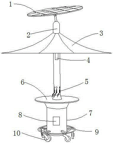
[0016] like figure 1 As shown, the mobile solar mobile phone charging pile with sunshade and rainproof structure includes solar panel 1, the charging pile also includes support rod 2, sunshade and rainproof structure 3, placement table 6 and support base 7, and solar panel 1 is movably connected At the top of the support rod 2, the sunshade and rainproof structure 3 is arranged on the support rod 2 below the solar cell panel 1, the bottom end of the support rod 2 is connected and fixed to the center of the upper surface of the table top 6, and the support base 7 is connected and fixed to the table top In the center of the bottom of 6, a flange ring 9 is arranged around the support base 7, and a plurality of universal rollers 10 are arranged under the circumference of the flange ring 9, and a transformer 4 is arranged inside the support rod 2. The support rod 2 is prov...


PUM


Abstract

A mobile solar phone charging pile with a sun shading and rain shielding structure belongs to the technical field of solar energy utilization. The mobile solar phone charging pile comprises a solar cell panel, a support bar, a sun shading and rain shielding structure, a placing desktop, and a support base. The mobile solar phone charging pile has the advantages of simple structure, convenient operation, and clear working principle. The solar cell panel and the support bar are movably connected by a hinge. The angle of the solar cell panel can be adjusted during installation according to the sun angle of a region. The support bar is equipped with the umbrella-like sun shading and rain shielding structure, which makes the charging pile more user-friendly. In the phone charging process, a user can sit and rest at the placing desktop and wait for the end of charging. A flange with rollers is arranged below the support base, so that the charging pile can be easily moved to a position with good sunlight. Solar energy is converted into electricity needed by phones. The way to get electricity is more energy-saving and environment-friendly. Electricity use is safer and more convenient.

Description

technical field [0001] The invention belongs to the technical field of solar energy utilization, and relates to a solar cell phone charging device, in particular to a mobile solar cell phone charging pile with a sunshade and rainproof structure. Background technique [0002] Mobile phones are a necessity in modern life, and their functions and advantages are self-evident. With the changing times, a variety of smart phones have emerged. However, the larger the screen of the mobile phone, the greater the power consumption. It often occurs that the power is cut off during the process of going out and the connection with the outside world is lost because there is no place to charge. At present, some shopping malls have been equipped with a coin-operated mobile phone charging device. After the coin is put in, the AC power supply is turned on, and the DC power output required by the mobile phone is realized through the AC-DC conversion device inside the device. Although this devic...

Claims


Application Information

Patent Timeline
Patent Type & Authority Applications(China)
IPC IPC(8): H02J7/00H02J7/35H02S20/30
CPCY02E10/50
Inventor 叶秀兰
Owner 叶秀兰
Why Eureka
Try Eureka