Front light module and display module

A front light module and display module technology, which is applied in the directions of optics, light guide, electric light source, etc., can solve the problems of limiting reflective display assembly, improvement, and display size increase, and achieves improved hot spots, good optical quality, and good Effect of Light Intensity Uniformity

Active Publication Date: 2019-09-10
E INK HLDG INC
View PDF16 Cites 0 Cited by
  • Summary
  • Abstract
  • Description
  • Claims
  • Application Information

AI Technical Summary

Problems solved by technology

[0004] Generally speaking, the way to solve the hot spot phenomenon is to make microstructures (such as serration microstructures) on the light incident surface of the light guide plate or to adjust the dot density of the light guide plate. However, due to the reduction of the number of light sources and the reflective display App display size increase, this approach has its limits
In addition, increasing the adjustment range of the dot density of the light guide plate will greatly increase the relative accuracy of the light source, which will limit the assembly of the reflective display.

Method used


Image

  • Front light module and display module
  • Front light module and display module
  • Front light module and display module

Examples


Embodiment Construction

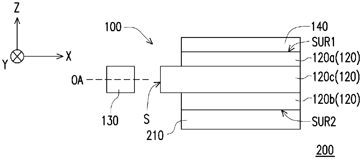
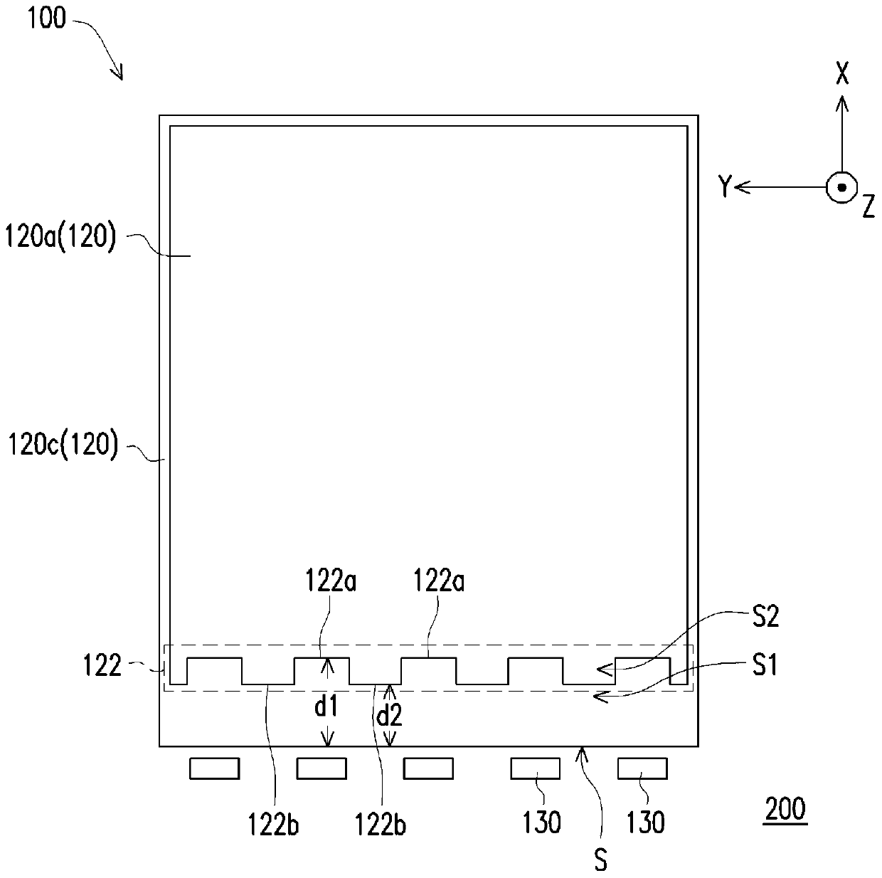
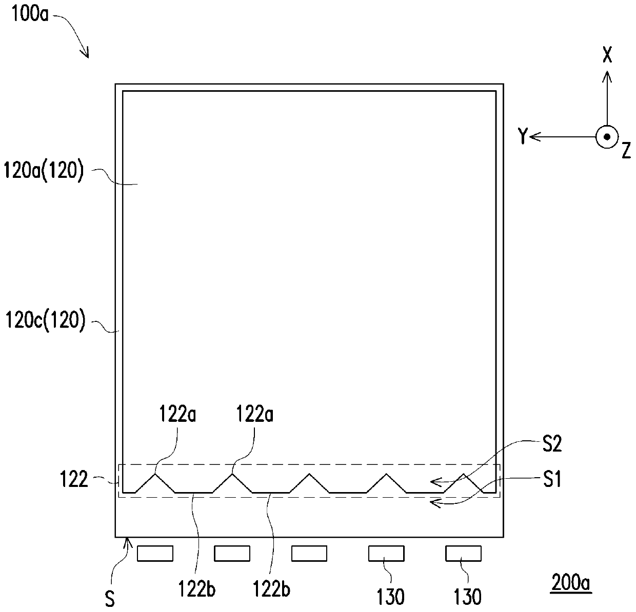
[0071] Figure 1A is a schematic cross-sectional view of a display module according to an embodiment of the present invention, Figure 1B for Figure 1A Example top view schematic. Figure 1C and Figure 1D They are schematic top views of display modules in different embodiments of the present invention. It should be noted that, in order to more clearly show the configuration relationship of the display modules in this embodiment, in Figure 1B The illustrated pattern of the functional layer 140 is omitted in FIG.

[0072] In order to describe the arrangement relationship of the display module 200 of this embodiment in detail, the display module 200 of this embodiment can be considered to be in a space constructed by the X axis, the Y axis and the Z axis, wherein the X axis direction is substantially the same as that of multiple axes. The directions of the optical axes OA of the light sources 130 are parallel and extend along the horizontal direction. The Z-axis direction ...


PUM


Abstract

The invention provides a front optical module and a display module. The front optical module comprises a plurality of stacked light-transmitting materials and a plurality of light sources. The light-transmitting materials comprise incident surfaces. The light sources are used for providing a plurality of light beams and are configured beside the incident surfaces. Edge parts are arranged on positions, adjacent to the light sources, on at least one of the light-transmitting materials, each edge part comprises a plurality of first sub-edges and second sub-edges, the first sub-edges correspond to the light sources, the first sub-edges and the second sub-edges are arranged into a column in a staggered way, and one of distances from the first sub-edges to the incident surfaces is larger than one of distances from the second sub-edges to the incident surfaces. In addition, the display module is also provided. By using the front optical module provided by the invention, the strength of light at the parts, close to the incident surfaces, of an area light source can be favorable in uniformity.

Description

technical field [0001] The invention relates to an optical module and a display module, in particular to a front light module and a display module. Background technique [0002] Generally speaking, the design of the reflective display (Reflective Display) with the front light module is to arrange the front light module above the display module, and set the light source on the side of the light guide panel (LGP), the light emitted by the light source The light can travel in the light guide plate in the form of total internal reflection, and break the total internal reflection behavior through the microstructure, and then refract towards the display module, converting the light source into a surface light source with uniform optical distribution. The light refracted towards the display module can be reflected by the display module and transmitted to the viewer. [0003] Traditionally, the front light module of a reflective display includes a light source, a light guide plate,...

Claims


Application Information

Patent Timeline
Patent Type & Authority Patents(China)
IPC IPC(8): F21S8/00F21V5/00F21V19/00F21V8/00F21V13/00G09F9/30
Inventor 廖经桓许财维
Owner E INK HLDG INC
Why Eureka
Try Eureka