
Path programming method and apparatus

A path planning and path technology, applied in the field of navigation, can solve the problems of a large number of search nodes, high search efficiency, and low search efficiency.

Inactive Publication Date: 2017-04-05
ALIBABA (CHINA) CO LTD
View PDF13 Cites 5 Cited by
  • Summary
  • Abstract
  • Description
  • Claims
  • Application Information

AI Technical Summary

Problems solved by technology

[0004] If the estimated distance value h(n) is less than or equal to the actual value of the distance from node n to the target node, the number of nodes to be searched in the path planning process is large, the searched map range is large, and the search efficiency is low, but the distance from the initial node to the target node can be obtained. The shortest path of the target node (optimal solution); if the estimated distance value h(n) is equal to the shortest distance from node n to the target node, the path search will be strictly along the shortest path during the path planning process, and the search efficiency at this time is The highest, although the shortest path (optimal solution) from the initial node to the target node can be obtained, but the number of searched nodes is still large, and the searched map range is still large; if the estimated distance value h(n) is greater than the actual distance value g(n), the number of nodes to be searched in the path planning process is small, the search map range is small, and the search efficiency is high, but the optimal solution cannot be guaranteed.
[0005] It can be seen that when using the A* algorithm for shortest path planning, it is necessary to search a large amount of map data to find the shortest path (optimal solution), which will lead to low path planning efficiency

Method used


Image

  • Path programming method and apparatus
  • Path programming method and apparatus
  • Path programming method and apparatus

Examples


Embodiment Construction

[0085] In order to make the purpose, technical solutions and advantages of the embodiments of the present invention clearer, the technical solutions in the embodiments of the present invention will be clearly and completely described below in conjunction with the drawings in the embodiments of the present invention. Obviously, the described embodiments It is a part of embodiments of the present invention, but not all embodiments. Based on the embodiments of the present invention, all other embodiments obtained by persons of ordinary skill in the art without making creative efforts belong to the protection scope of the present invention.

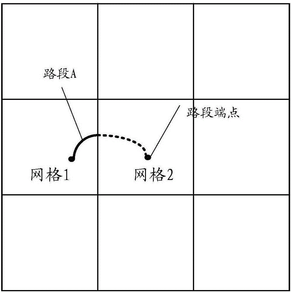
[0086] In order to facilitate the understanding of the embodiments of the present invention, before introducing the embodiments of the present invention, a brief introduction to the map itself is given first: maps are divided into layers, that is, a map can be composed of one or more layers, and each layer Divided into multiple grids. Among ...


PUM


Abstract

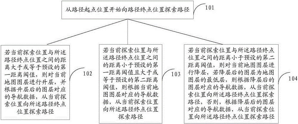
The invention discloses a path programming method and apparatus. The method comprises the following steps: rising a current map layer if a distance between a current search position and a path end point position is greater than or equal to a first distance threshold, and searching a path from the current search position to the path end point position according to navigation data corresponding to the risen map layer; searching a path from the current search position to the path end point position according to navigation data corresponding to the current map layer if a distance between the current search position and the path end point position is less than the first distance threshold and is greater than or equal to a second distance threshold; and lowering the current map layer if a distance between the current search position and the path end point position is less than the second distance threshold, searching a path from the current search position to the path end point position according to navigation data corresponding to the lowered map layer if the lowered map layer is a lowest map layer, and searching a path from the current search position to the path end point position according to the navigation data corresponding to the lowered map layer if the lowered map layer is not the lowest map layer.

Description

technical field [0001] The invention relates to the technical field of navigation, in particular to a path planning method and device. Background technique [0002] The general path planning method in the field of navigation is the A* algorithm, which is the most effective method for solving the shortest path in the static road network. [0003] The A* algorithm formula is expressed as: f(n)=g(n)+h(n), where f(n) is the evaluation function from the initial node to the target node via n nodes, and g(n) is the value in the state space The actual cost from the initial node to n nodes in h(n) is the estimated cost of the best path from n nodes to the target node. The key to ensure the condition of finding the shortest path (optimal solution) lies in the selection of the evaluation function f(n). Since g(n) in the evaluation function f(n) is fixed, the key actually lies in the selection of h(n) : [0004] If the estimated distance value h(n) is less than or equal to the actual...

Claims


Application Information

Patent Timeline
IPC IPC(8): G01C21/34
CPCG01C21/34G01C21/3446
Inventor 鲍建军
Owner ALIBABA (CHINA) CO LTD
Learn More