Condensed water collector

A technology of condensate and collector, which is applied in the direction of instruments, steam condensation, thermoelectric condensation, etc., can solve the problems of interfering with the sampling process and damaging the components of the chamber, and achieve the effect that is not easy to make mistakes

Active Publication Date: 2017-04-05
F HOFFMANN LA ROCHE & CO AG
View PDF6 Cites 4 Cited by
  • Summary
  • Abstract
  • Description
  • Claims
  • Application Information

AI Technical Summary

Problems solved by technology

Condensation formation can have various adverse effects
For example, condensation may drip into or onto containers located inside the chamber, or onto other sensitive parts of the chamber, thereby interfering with the sampling process or damaging chamber components

Method used


Image

  • Condensed water collector
  • Condensed water collector
  • Condensed water collector

Examples


Embodiment Construction

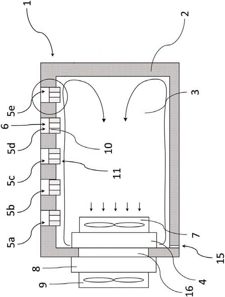
[0024] The chamber containing the condensate collector and the method of removing condensate from the chamber of the present invention will be discussed in more detail subsequently.

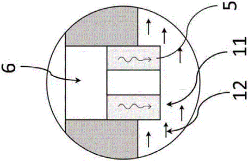
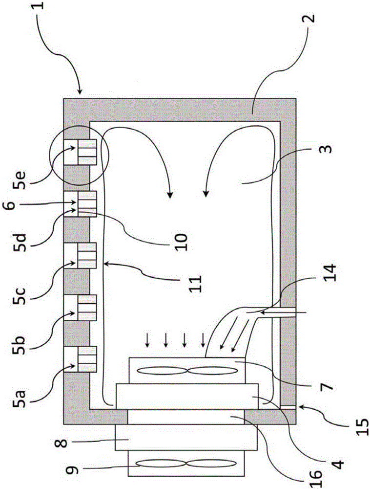
[0025] First, combine the Figure 1a and Figure 1b Different aspects of the chamber of the present invention are discussed. Then, combine the Figure 2a to Figure 6 Alternative or additional aspects of the chamber of the invention are detailed. Figure 1a The illustrated chamber 1 comprising at least one target area 6 prone to condensation water formation comprises at least one condensation water collector 5a-5e comprising at least one first part 10 and at least one second part 11 , the first part 10 is arranged to collect condensed water from the at least one target area, the second part 11 is outside the at least one target area, including being arranged between the first part 10 and the second part 11 and is configured to deliver the collected Porous material for condensed water, the chambe...


PUM

PropertyMeasurementUnit
diameteraaaaaaaaaa

Abstract

One aspect of the present disclosure relates to a compartment comprising at least one target area susceptible to condensed water formation includes at least one condensed water collector, the condensed water collector comprising at least a first portion arranged to collect condensed water from the at least one target area and at least a second portion outside of the at least one target area, and further including a porous material arranged between the first portion and the second portion and being configured to transport the collected condensed water, the compartment further including a condensed water remover configured to remove condensed water from the second portion thereby facilitating transportation of condensed water from the first portion to the second portion via the porous material.

Description

technical field [0001] The invention relates to a chamber comprising a condensate collector. Background technique [0002] In some known analytical system compartments (eg, reagent container compartments or sample container compartments), the formation of condensation water can be a problem. For example, in order to gain access to a container inside a chamber, eg to sample material from the container, access to the interior of the chamber is necessary. On the other hand, the inner space of the chamber can be cooled. In this case, condensed water may condense. For example, condensation may form near or at openings through which the container inside the chamber is accessed. The formation of condensate can have various adverse effects. For example, condensed water may drip into or onto containers located inside the chamber, or onto other sensitive components of the chamber, thereby interfering with the sampling process or damaging components of the chamber. Condensation wa...

Claims


Application Information

Patent Timeline
Patent Type & Authority Applications(China)
IPC IPC(8): G01N37/00
CPCG01N37/00G01D11/00B01D1/14B01D5/0042B01D5/006B01L1/00B01L2200/141B01L2200/142B01L2300/069B01L2300/161B01L2300/1822B01L2300/1894B01L2400/0406B01L2400/0457F25D21/14F25D2321/147
Inventor C·马蒂B·R·维德默M·杰齐奥尔斯基
Owner F HOFFMANN LA ROCHE & CO AG
Why Eureka
Try Eureka