Method and system for examining cutter compensation parameters based on numerical control machine

A tool compensation, CNC machine tool technology, applied in the field of control systems, can solve the problems of incorrect tool compensation parameters, machining accidents, etc., to prevent machining accidents, avoid negligence, and eliminate errors.

Active Publication Date: 2017-04-05
SHANGHAI ELECTRIC POWER GENERATION EQUIPMENT CO LTD
View PDF3 Cites 7 Cited by
  • Summary
  • Abstract
  • Description
  • Claims
  • Application Information

AI Technical Summary

Problems solved by technology

[0005] In view of the shortcomings of the prior art described above, the purpose of the present invention is to provide a method and system for verifying tool compensation parameters based on CNC machine tools, which is used to solve various problems caused by incorrect tool compensation parameters in the prior art. The problem of processing accidents

Method used


Image

  • Method and system for examining cutter compensation parameters based on numerical control machine
  • Method and system for examining cutter compensation parameters based on numerical control machine
  • Method and system for examining cutter compensation parameters based on numerical control machine

Examples


Embodiment 1

[0031] This embodiment discloses a method for verifying tool compensation parameters based on a numerically controlled machine tool, which is used to verify the correctness of tool compensation parameters.

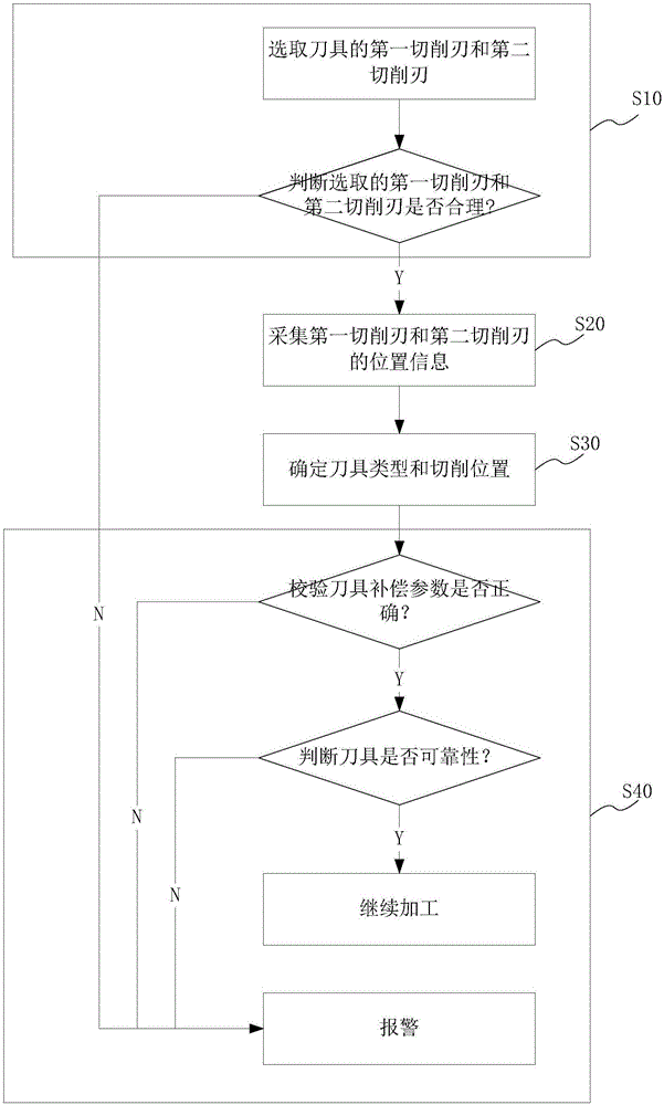
[0032] like figure 1 As shown, the verification method of the tool compensation parameters of the CNC machine tool of the present embodiment includes:

[0033] Step S10, select the first cutting edge and the second cutting edge of the tool:

[0034] Generally, it is stipulated that the lower cutting edge of the straight groove cutter of the vertical lathe is the first cutting edge; the cutting edge of the curved groove cutter is the cutting edge that can directly face the inner and outer circular surfaces as the preferred cutting edge, and the inner circle of the curved groove cutter The first cutting edge at the position is the right cutting edge; the first cutting edge at the outer circle position is the left cutting edge.

[0035] Among them, each cutting edge of the ...

Embodiment 2

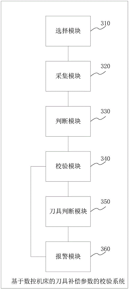
[0067] This embodiment discloses a calibration system for tool compensation parameters based on CNC machine tools, such as image 3 shown, including:

[0068] A selection module 310, configured to select the first cutting edge and the second cutting edge.

[0069] The collection module 320 is used to collect the position information of the first cutting edge and the second cutting edge, wherein the position information refers to the coordinate information of the tip of the cutting edge, the X coordinate is the X-direction parameter, and the Z coordinate is the Z-direction parameter.

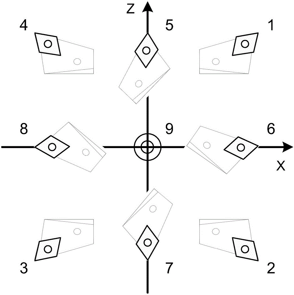
[0070] The judging module 330 is configured to judge the tool type and cutting position according to the position information of the first cutting edge and the position information of the second cutting edge. Wherein, the tool type includes but not limited to straight groove cutter and curved groove cutter, and the cutting position includes but not limited to inner circle position and outer circ...


PUM


Abstract

The invention provides a method and system for examining cutter compensation parameters based on a numerical control machine. The method includes the following steps: selecting a first cutting edge and a second cutting edge of a cutter; acquiring the position information of the first cutter edge and the second cutter edge; based on the position information of the first cutter edge and the second cutter edge, determining the type of the cutter and the cutting position of the cutter; based on the type of the cutter and the cutting position of the cutter, examining the cutter compensation parameters of the numerical control machine in line with by a X-direction parameter difference between the first cutting edge and the second cutting edge and a Z-direction parameter difference between the first cutting edge and the second cutting edge, and sounding alarm if the cutter compensation parameters are examined to be incorrect. According to the invention, the method effectively prevents machining accidents caused by cutter compensation parameters of all kinds of cutters, avoids negligence, and eliminates the possibility of errors in the cutter compensation parameters.

Description

technical field [0001] The invention relates to a control system in the process of machining a workpiece by a numerical control machine tool, in particular to a method and system for checking tool compensation parameters based on a numerical control machine tool. Background technique [0002] With the development and popularization of numerical control technology, the requirements for the skills of operators in production are getting higher and higher. CNC (Computer Numerical Control) is the abbreviation of computer numerical control machine tool, which is an automatic machine tool controlled by program. The control system can logically process the program specified by the control code or other symbolic instructions, and decode it through the computer, so that the machine tool can perform the specified action, and the blank can be processed into semi-finished or finished parts through tool cutting. [0003] In the process of CNC machining, especially in the machining of CNC ...

Claims


Application Information

Patent Timeline
Patent Type & Authority Applications(China)
IPC IPC(8): G05B19/404
CPCG05B19/404G05B2219/50058
Inventor 庄秋峰刘心蕊冀龙涛张鹤李芳李梦晨
Owner SHANGHAI ELECTRIC POWER GENERATION EQUIPMENT CO LTD
Why Eureka
Try Eureka