Blowing Device

A technology of air supply device and air supply fan, which is applied to hair drying device, parts of pumping device for elastic fluid, device for washing hair or scalp, etc. , The effect of reducing fan noise and suppressing noise

Active Publication Date: 2017-04-12
MAXELL HLDG LTD
View PDF5 Cites 4 Cited by
  • Summary
  • Abstract
  • Description
  • Claims
  • Application Information

AI Technical Summary

Problems solved by technology

[0005] In the axial flow fan disclosed in Patent Document 1, since the trailing edge of the blade is formed by a single arc, the airflow on the press...

Method used


Image

  • Blowing Device
  • Blowing Device
  • Blowing Device

Examples


Embodiment Construction

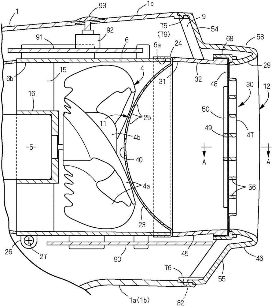
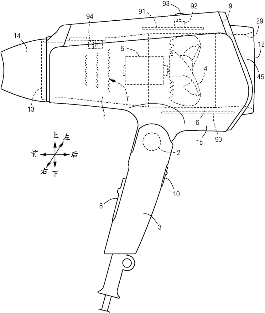
[0032] (Example) Figure 1 to Figure 11 This shows an embodiment in which the blower of the present invention is applied to a hair dryer. In the present invention, the front and back, left and right, up and down follow figure 2 The cross arrows shown and the front, back, left and right, and up and down displays marked near the arrow. figure 2 Among them, the hair dryer is provided with a main body casing 1 composed of a hollow cylinder, and a handle 3 foldably connected to the main body casing 1 with a shaft 2 as the center.

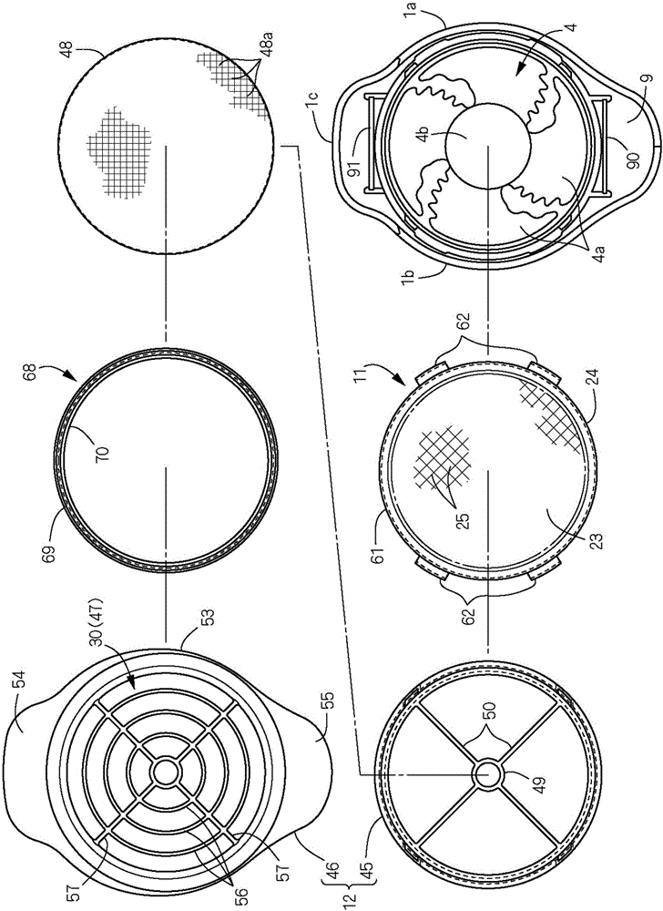
[0033] figure 1 as well as figure 2 Here, the main body casing 1 is formed by joining the left and right divided casings 1a, 1b and the upper casing 1c to form a hollow cylindrical shape, and is provided with a rear opening 9 at the rear end and a blower outlet 13 at the front end. Arranged inside the main body casing 1 are an axial blower fan 4 that delivers dry air, a motor 5 that drives the fan 4 and rotates it, and a cylindrical fan case that support...


PUM


Abstract

The present invention provides a blowing device which can restrain the noise generated by the blades of a blowing fan. The blowing fan 4 is arranged in a shell 6 possessing an inlet 6a and an outlet 6b and is equipped with a plurality of fan blades 4a around a fan boss 4b. The front concave flanges 85 and the back concave flanges 86 are respectively formed at the blade front edges and the blade back edges of the fan blades 4a to reduce the fan noise. The adjacent spacing P1 of the concave parts 85a of the front concave flanges 85 is set to be greater than the adjacent spacing P2 of the concave parts 86a of the back concave flanges 86.

Description

Technical field [0001] The present invention relates to an air blowing device mounted on a hair dryer and the like, and more particularly to an air blowing device capable of reducing the amount of air blowing noise during use. Background technique [0002] Regarding the present invention, Patent Document 1 discloses a structure of a blower fan in which a plurality of fan blades are provided on the outer periphery of a fan boss. Among them, an axial flow fan having a plurality of blades integrally provided on the outer circumference of the protruding portion is provided inside a cylindrical casing. The plurality of blades are provided with a pressure surface on one side that squeezes air and a negative pressure surface on the opposite side. [0003] Prior art literature [0004] Patent Document 1: Japanese Patent Application Publication No. 9-191924 [0005] In the axial flow fan of Patent Document 1, since the trailing edge of the blade is formed by a circular arc, the airflow on th...

Claims


Application Information

Patent Timeline
IPC IPC(8): A45D20/12F04D29/38F04D29/66
CPCA45D20/12F04D29/388F04D29/666F05D2240/303F05D2240/304
Inventor 友寄泰秀冈本佑介
Owner MAXELL HLDG LTD
Why Eureka
Try Eureka