
A kind of non-contact digital driver controller

A driver controller, digital technology, applied in locomotives and other directions, can solve the problems of high wiring cost, many layout restrictions, limited number of codes, etc., to improve control accuracy and real-time performance, overcome many layout restrictions, and overcome the volume. huge effect

Active Publication Date: 2019-03-01
SHANGHAI IRM TOUCH ELECTRONICS TECH
View PDF6 Cites 0 Cited by
  • Summary
  • Abstract
  • Description
  • Claims
  • Application Information

AI Technical Summary

Problems solved by technology

However, because it can only output preset values ​​at the encoding place, and the amount of encoding is limited by the volume of the encoder, this type of encoder may be huge and occupy a lot of space on the console. Due to the limited encoding, the output accuracy is not high, for example : Patent No. CN200620052707, the use of non-contact magnetic pulse encoder avoids the core shortcomings of the contact driver controller, but due to the traditional double-handle design and the presence of encoders, its volume is still very large and limited by the number of codes , unable to achieve continuous output of stepless
[0004] In addition, most of the above two types of driver controllers do not have the bus communication function, and wiring needs to be set up separately between related controllers, resulting in many layout restrictions, high wiring costs, and low reliability, which is not conducive to the distribution of equipment. type control

Method used

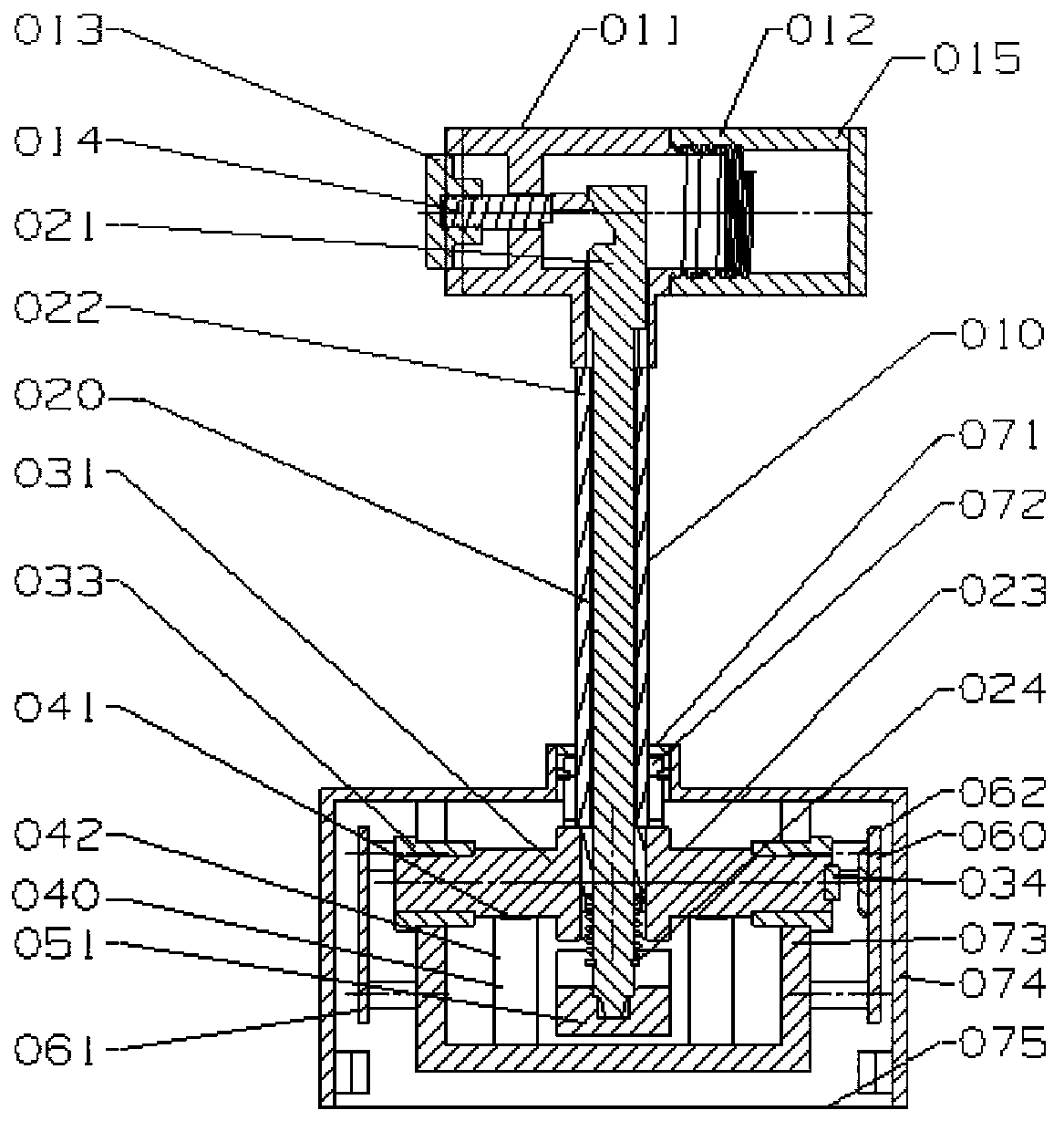
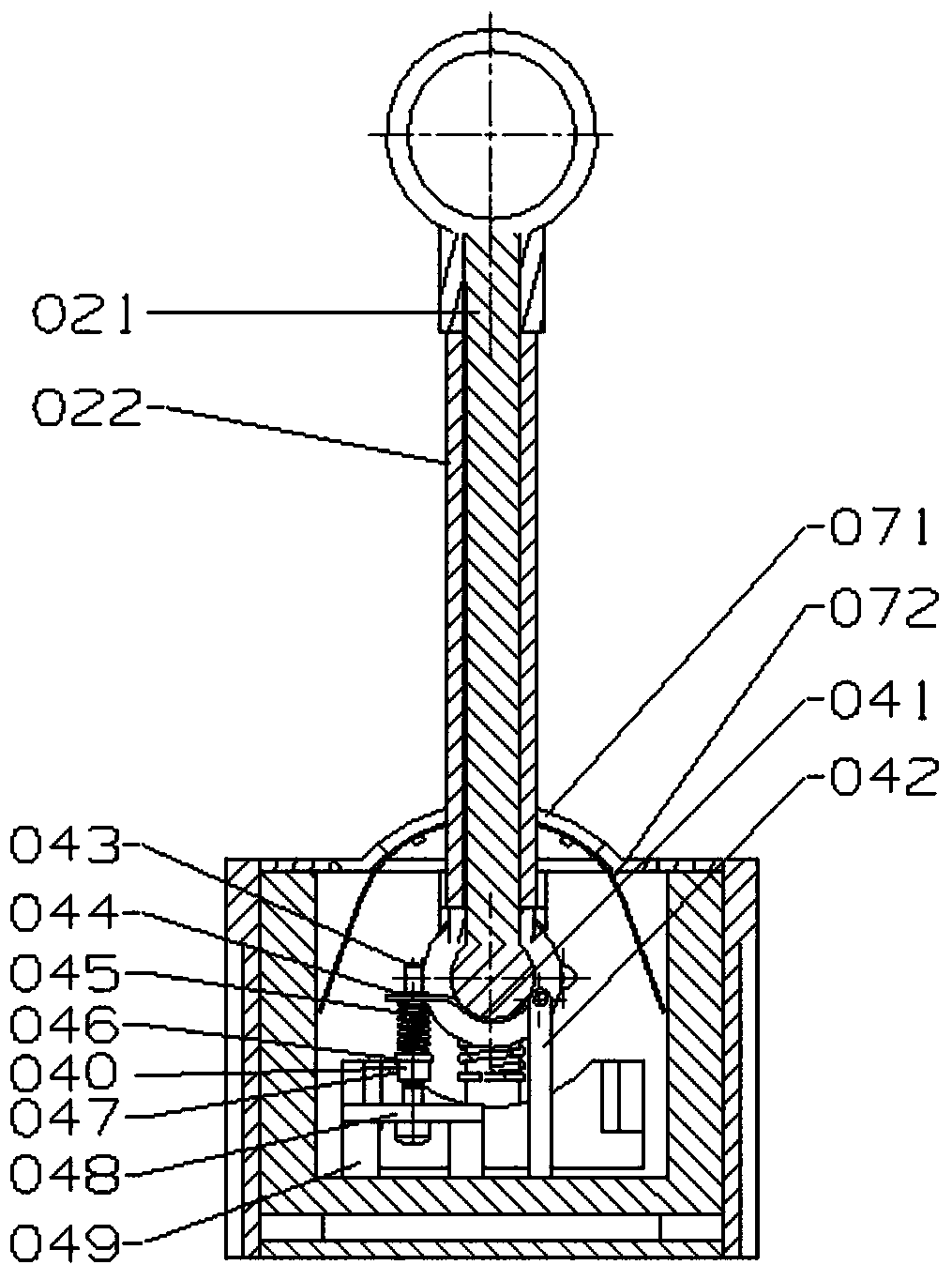
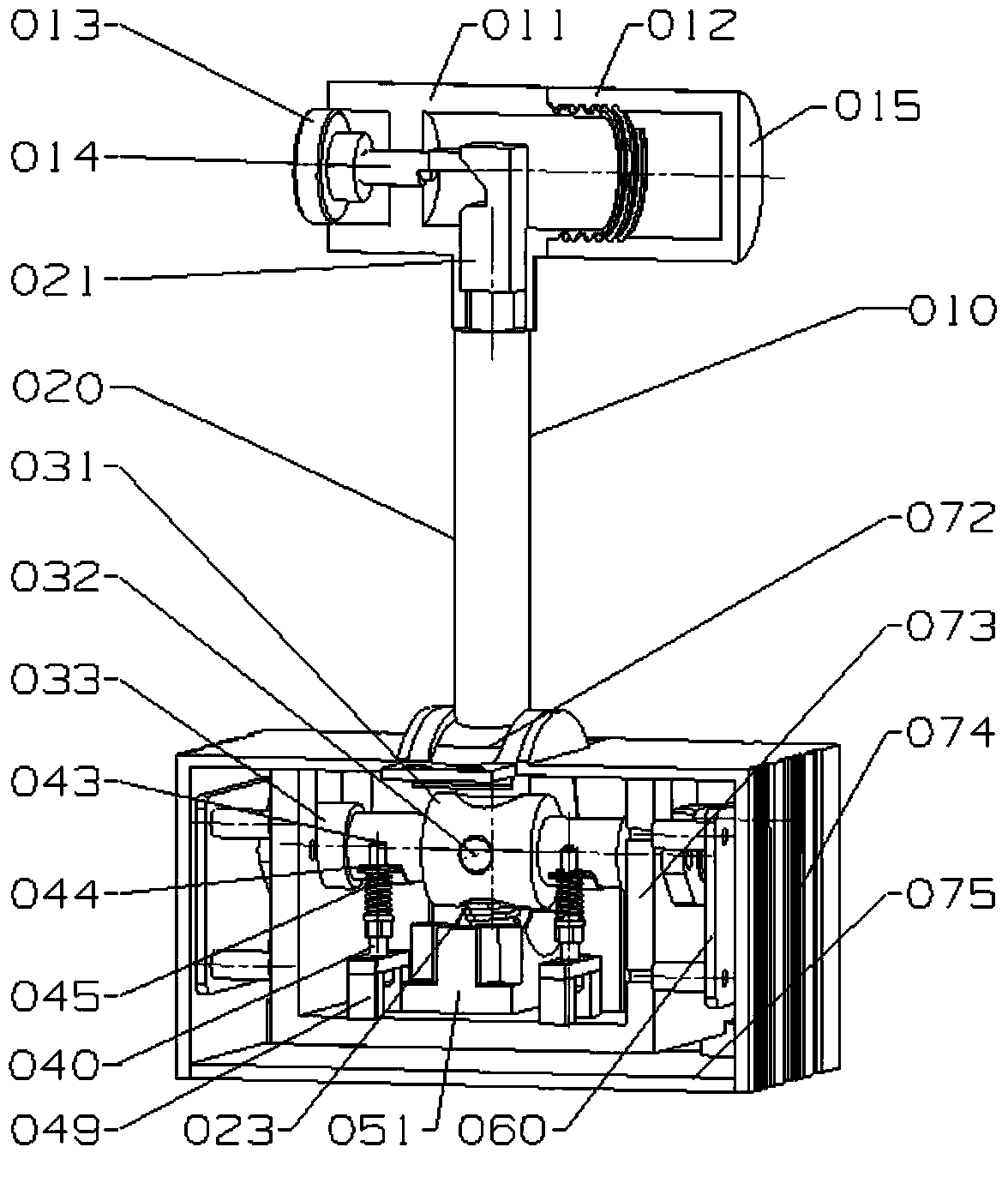

Image

  • A kind of non-contact digital driver controller
  • A kind of non-contact digital driver controller
  • A kind of non-contact digital driver controller

Examples


Embodiment Construction

[0023] The following will clearly and completely describe the technical solutions in the embodiments of the present invention with reference to the accompanying drawings in the embodiments of the present invention. Obviously, the described embodiments are only some, not all, embodiments of the present invention. Based on the embodiments of the present invention, all other embodiments obtained by persons of ordinary skill in the art without making creative efforts belong to the protection scope of the present invention.

[0024] Such as figure 1 , figure 2 , image 3 and Figure 4 As shown, a non-contact digital driver controller, the non-contact digital driver controller includes a housing 074, a mounting base 073, a rotating handle structure 010, a position sensor chip 063 and a main board 060, and the rotating handle structure 010 It includes a handle 015, a push rod mechanism 020 and a rotating shaft 031. The handle 015 is provided with a push pin 014. The push rod mech...


PUM


Abstract

The invention discloses a non-contact digital driver controller, which comprises a rotation handle structure, a magnet, a position sensor chip and a main board, wherein the magnet is arranged on a rotation shaft and coaxially rotates along with the rotation shaft at the same angular velocity, the position sensor senses the rotation angle of the magnet, and CAN frame is encapsulated after the consistent output is confirmed by the microcontroller on the main board and is treated by a traction / braking system. According to the present invention, the structure of the rotation handle structure allows movements toward two directions so as to control the two directions such as locomotive advancing and locomotive retreating while the handle turning angle and the locomotive speed control are correlated through the position sensor and the main board, the non-contact sensing design is used, the starting torque is small, and the smoothness is high; and the single handle control and output is stepless, and the driving direction and the speed giving are integrated, such that the disadvantages of large volume, touch point wear, short service life, more maintenance, non-continuous output and the like of the old driver controller are overcome, and the r small, intelligent and reliable requirements of the new generation of the driver controller are met.

Description

technical field [0001] The invention relates to the technical field of locomotive control, in particular to a non-contact digital driver controller. Background technique [0002] The driver controller is the main electrical appliance that directly controls the driving of the rail engineering vehicle. Its main function is to judge the direction in which the driver pushes the handle or turns the handwheel through a certain type of sensor, and converts the corresponding angular displacement into an electrical signal and outputs it to the traction / Braking system to realize the start, stop and speed regulation of the locomotive. Since rail vehicle operations are mostly required to be completed within a certain operating window, there are high requirements for the reliability and life of the components. At the same time, the accuracy and efficiency of the operation also put forward relatively high requirements for the smoothness and output accuracy of the driver's controller. h...

Claims


Application Information

Patent Timeline
Patent Type & Authority Patents(China)
IPC IPC(8): B61C17/00
CPCB61C17/00
Inventor 张宇明赵雷
Owner SHANGHAI IRM TOUCH ELECTRONICS TECH
Learn More