Laser leading beacon optical system

A technology of optical system and projection optical system, applied in the direction of optics, optical components, electric light source, etc., can solve the problems of navigation safety hazards, difficult to identify guide lights, difficult to identify navigation aids, etc., and achieve high transmittance, high Visibility, high directional effects

Inactive Publication Date: 2017-04-19
SHANGHAI RADIO EQUIP RES INST
9 Cites 4 Cited by

AI-Extracted Technical Summary

Problems solved by technology

The implementation methods of the above-mentioned navigation lights all use LED light-emitting diodes as the main light source. The characteristics of the LED itself determine that it has a great deficiency in the quality of the navigation beam: first, when the wharf is operated at night, a large number of lighting facilities are put into use, and the guides set by the navigation mark department are surrounded by li...

Method used

Beam adjustment and shaping unit 3 respectively carries out shaping to red light, green light laser beam, and it comprises: first lens group 31 and second lens group 32; Described first lens group 31 comprises two cylindrical mirrors , the red laser beam is incident as a square beam, compressed into a rectangular spot after passing through two cylindrical mirrors; the second lens group 32 includes two spherical mirrors and two cylindrical mirrors, and the green laser beam is incident as a circular beam , which are compressed into an elliptical spot after passing through two spherical mirrors and two cylindrical mirrors (an optical system in the form of a Galilean telescope). It is worth noting that the diameter of the circular spot of green light after collimation should be slightly larger than the width of the slit, so as to ensure that the elliptical spot compressed by the cylindrical mirror can fill the entire slit area. The reshaped elliptical spot is inscribed in the slit window, which can satisfy the spot to completely fill the slit area, while ensuring efficient use of energy. In addition, the optical system of the shaping unit adopts a Galilean telescope structure, so that the light intensity distribution is uniform and moderate.
Described aperture 4 is used for restricting the boundary of the laser beam after shaping, and the laser beam after shaping passes through aperture, and its sharp aperture boundary has guaranteed the high sharpness of beam edge, and visual boundary is clear, can Get higher navigation accuracy. The aperture size in this example is calculated by the formula li=ftanθi, where: f is the focal length of the projection system, and θi is the horizontal divergence angle or pitch divergence angle of the system. By precisely adjusting the size of the aperture window, accurate coverage of the entire navigation channel area can be ensured. The size of the aperture in this example does not need to be adjusted in the post-adjustment, but there is a very high precision requirement for the size of the aperture, so the a...

Abstract

A laser leading beacon optical system disclosed by the present invention comprises an adjusting pedestal, a light source laser arranged on the adjusting pedestal, a light beam adjusting and shaping unit, a diaphragm, a projection optical system and a protection window. The light source laser emits a laser beam to pass the light beam adjusting and shaping unit, the diaphragm and the projection optical system, and finally the laser beam is emitted out from the protection window. According to the present invention, the red and green two fan-shaped light beams of high visibility, high transmissivity and high directivity are generated for the laser leading beacon system, the two light beams are located in a same plane, and the boundaries of the two light beams have some overlap, so that the marine navigators can be navigated on the severe weather conditions, such as the rain, the fog, etc.

Application Domain

LighthouseRefractors +2

Technology Topic

TransmittanceDirectivity +5

Image

  • Laser leading beacon optical system
  • Laser leading beacon optical system
  • Laser leading beacon optical system

Examples

  • Experimental program(1)

Example Embodiment

[0023] The present invention will be further elaborated below by describing a preferred specific embodiment in detail in conjunction with the accompanying drawings.
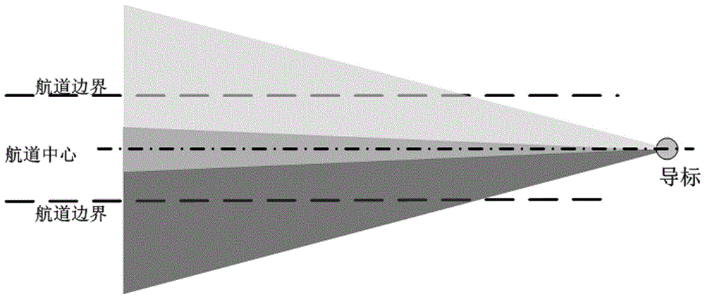
[0024] The invention provides an optical system design scheme of a laser guide, which uses red and green light for navigation. The optical system needs to provide such as figure 1 The red and green parallel fan-shaped light beams shown have a certain overlapping area at the boundary, and it is necessary to ensure that the entire navigation area is covered. At the same time, the optical system should ensure the high resolution of the laser beam projected on the channel and the efficient use of energy. Therefore, it is necessary to ensure the uniformity of the intensity distribution of the exit spot and the minimum energy loss during the shaping process.
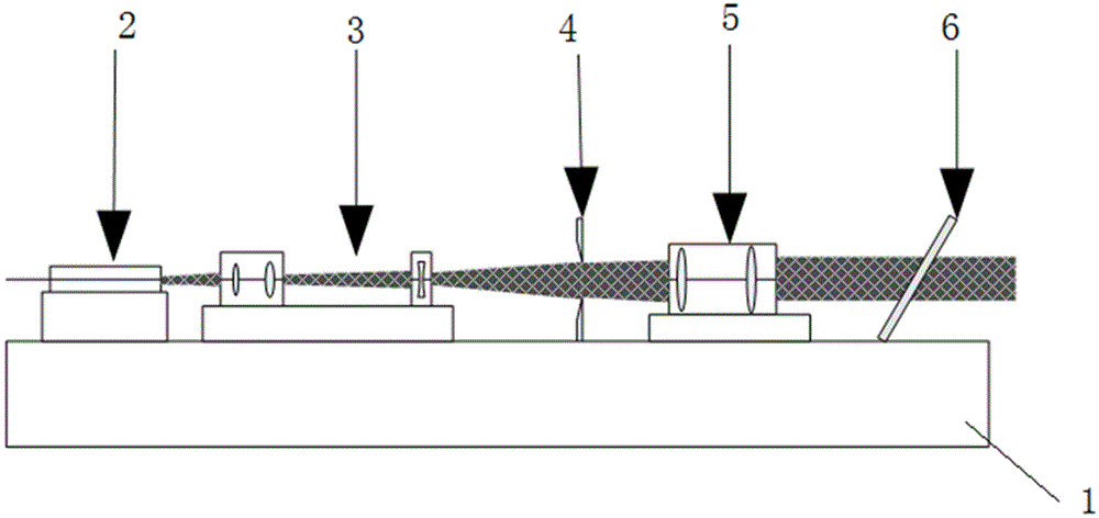
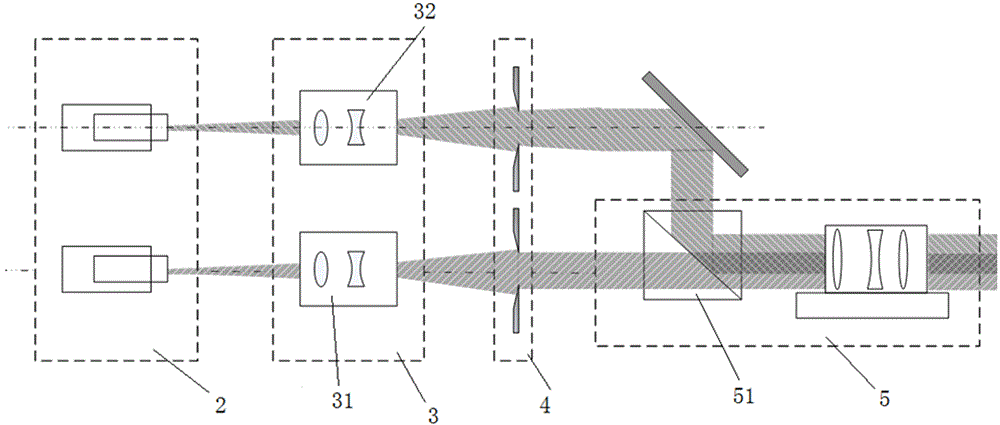
[0025] The optical system of the laser guide, such as figure 2 As shown, it includes an adjustment base 1; a light source laser 2 arranged on the adjustment base, a beam adjustment and shaping unit 3, an aperture 4, a projection optical system 5 and a protective window 6; the light source laser 2 emits a laser beam that passes through the beam adjustment Correcting and shaping unit 3 , aperture 4 , projection optical system 5 , and finally projected from the protective window 6 . Its main optical path design diagram is as follows: image 3 As shown, the two beams of red and green light are respectively shaped and adjusted by the aperture, combined by the beam combining prism, and then enlarged and projected by the projection system.
[0026] The source laser consists of a red laser with a wavelength of 635nm±10nm and a green laser with a wavelength of 532nm±10nm. The emission power of the laser should be determined according to factors such as navigation range, navigation environment, and human eye resolution. In order to ensure the efficient utilization of subsequent energy, the selected laser must have good beam quality, so as to reduce the design and adjustment pressure of the subsequent optical shaping system. The red laser selected in this example is a 5W laser with a square light emitting surface of 8mm*8mm, and the green laser is a 5W laser with a circular light emitting surface of 3mm in diameter. The above-mentioned lasers are lasers with higher emission power and better emission beam quality among similar products. In order to achieve a certain overlap of the red and green fan-shaped beams at the boundary, both the red and green lights need to have a certain offset from the symmetric axis of the optical path center, and the offset can be calculated by the formula l 偏移 =ftanθ 边界 Calculate, where f is the focal length of the projection system, θ 边界 is the boundary angle, l 偏移 is the offset. When the laser is placed, the center of the light-emitting surface is offset from the central axis by l 偏移 place. In this example, the red and green beams are respectively incident from the A and B sides of the beam-combining prism, and the center of the light-emitting area of ​​the red laser is shifted downward by l based on the horizontal central axis of the beam-splitting prism. 偏移; The center of the light-emitting area of ​​the green laser is based on the vertical central axis of the beam combining prism, and shifts to the left by l 偏移.
[0027] The light beam adjustment and shaping unit 3 respectively shapes the red and green laser beams, which includes: a first lens group 31 and a second lens group 32; the first lens group 31 includes two cylindrical mirrors, the red light The laser beam is incident as a square beam and is compressed into a rectangular spot after passing through two cylindrical mirrors; the second lens group 32 includes two spherical mirrors and two cylindrical mirrors, and the green laser beam is incident as a circular beam and passes through the Two spherical mirrors and two cylindrical mirrors (an optical system in the form of a Galilean telescope) are compressed into an elliptical spot. It is worth noting that the diameter of the circular spot of green light after collimation should be slightly larger than the width of the slit, so as to ensure that the elliptical spot compressed by the cylindrical mirror can fill the entire slit area. The reshaped elliptical spot is inscribed in the slit window, which can satisfy the spot to completely fill the slit area, while ensuring efficient use of energy. In addition, the optical system of the shaping unit adopts a Galilean telescope structure, so that the light intensity distribution is uniform and moderate.
[0028] The aperture 4 is used to constrain the boundary of the reshaped laser beam. The reshaped laser beam passes through the aperture, and its sharp aperture boundary ensures the high sharpness of the beam edge. The visual boundary is clear and can obtain higher Navigation accuracy. The aperture size in this example is given by the formula l i =ftanθ i Calculate, where: f is the focal length of the projection system, θ i is the horizontal divergence angle or pitch divergence angle of the system. By precisely adjusting the size of the aperture window, accurate coverage of the entire navigation channel area can be ensured. The size of the aperture in this example does not need to be adjusted in the later adjustment, but there is a very high requirement for the accuracy of the aperture size, so the aperture used in this example is an etched slit. This type of slit is small in size, high in precision, light in weight, and easy to assemble and fix. The precision of the slit used in this example is ±0.005mm, and the thickness is only 2mm. During the assembly process, it is only necessary to fine-tune the front and rear positions and pitch angles of the slit.
[0029] like image 3 , 4 As shown in , the projection optics project the shaped, apertured beam onto the desired course line. The projection optical system 5 includes a beam-combining prism 51, the beam-combining prism is respectively provided with first, second, and third surfaces (A, B, C), wherein the second surface B is in phase with the first surface A Vertically, the third surface C is parallel to the first surface A; the red and green laser beams are incident from the first and second surfaces of the beam combining prism respectively, and exit from the third surface at the same time. The projection optical system designed in this example is designed by codeV optical design software and simulated. Considering the overall system size, image quality and the number of lenses in the optical system, the focal length of the projection system in this example is set to 400mm. The final design result is composed of four spherical lenses and a cubic beam combining prism, with a total length of 350mm and a maximum lens diameter of about 50mm. Zoom in on the projection. It is worth pointing out that the red and green laser beams share the same projection system, which reduces the complexity of the system and reduces the size and weight of the system.
[0030] The optical adjustment support is used to fix the lens of the shaping optical system and the projection optical system. Due to the position of the lens, especially the projection system, high-precision position distance, pitch angle and the concentricity of each lens are required. Therefore, the adjustment support not only has the function of fixing the lens, but also needs a certain amount of adjustment, so that the lens can be fine-tuned.
[0031] The protective window ensures that the laser can pass through the light window with high transmittance. At the same time, it can also protect the lens and internal components from corrosion interference from environmental factors such as seawater and salt spray. In this example, the light window of K9 material is used, and an anti-reflection coating with a transmittance of 99% is coated to ensure efficient use of energy.
[0032]In summary, the present invention is a laser guide optical system, which produces two fan-shaped beams of red and green with high visibility, high transmittance, and high directionality for the laser guide system. The two beams are on the same plane and have a certain boundary. overlap. It can navigate for ship drivers in bad weather conditions such as rain and fog.
[0033] Although the content of the present invention has been described in detail through the above preferred embodiments, it should be understood that the above description should not be considered as limiting the present invention. Various modifications and alterations to the present invention will become apparent to those skilled in the art upon reading the foregoing disclosure. Therefore, the protection scope of the present invention should be defined by the appended claims.

PUM

no PUM

Description & Claims & Application Information

We can also present the details of the Description, Claims and Application information to help users get a comprehensive understanding of the technical details of the patent, such as background art, summary of invention, brief description of drawings, description of embodiments, and other original content. On the other hand, users can also determine the specific scope of protection of the technology through the list of claims; as well as understand the changes in the life cycle of the technology with the presentation of the patent timeline. Login to view more.

Similar technology patents

Vehicle-mounted projection system

InactiveCN104833367Aimprove visibilityGuaranteed projection effect
Owner:BOE TECH GRP CO LTD

Vehicular Lamp

ActiveUS20130265790A1improve visibility
Owner:KOITO MFG CO LTD

Electronics shell decoration with two-side three-dimensional texture effect

InactiveCN104363725AImprove visibilityImproved touch realism
Owner:东莞市汇诚塑胶金属制品有限公司

Operation panel device and image forming apparatus provided therewith

InactiveUS20120243042A1improve visibility
Owner:KONICA MINOLTA BUSINESS TECH INC

Classification and recommendation of technical efficacy words

  • improve visibility
  • Improve transmittance

Object display system in a virtual world

InactiveUS20050179685A1improve visibility
Owner:SONY COMPUTER ENTERTAINMENT INC

Scrolling items on a list

ActiveUS20060075358A1fast scroll speedimprove visibility
Owner:GULA CONSULTING LLC

Occlusion reducing transformations for three-dimensional detail-in-context viewing

InactiveUS7280105B2improve visibilityeffectively generate
Owner:INTELLECTUAL VENTURES ASSETS 186 LLC

LCD panel and method for forming the same

ActiveUS20120274869A1improve transmittanceaperture ratio be raise
Owner:TCL CHINA STAR OPTOELECTRONICS TECH CO LTD
Why Eureka
Try Eureka