
Method and device for controlling turn-on time of power switch tube in electromagnetic heating system

A power switching tube and heating system technology, applied in the direction of induction heating control, induction heating device, induction heating, etc., can solve the problems of increased switching loss, easy breakdown, overcurrent breakdown, etc., and prevent the turn-on time from being too long , Prevent large switching loss and prevent overcurrent breakdown

Active Publication Date: 2019-09-27
FOSHAN SHUNDE MIDEA ELECTRICAL HEATING APPLIANCES MFG CO LTD +1
View PDF4 Cites 0 Cited by
  • Summary
  • Abstract
  • Description
  • Claims
  • Application Information

AI Technical Summary

Problems solved by technology

[0002] In the working process of the relevant electromagnetic heating system, the turn-on time of the power switch tube is too short or too long, which will bring adverse effects
When the turn-on time of the power switch tube is too short, the switching frequency increases and the switching loss increases, which easily leads to less energy storage in the coil disk at a time, and the resonant circuit cannot oscillate to a low voltage, and the turn-on voltage of the power switch tube is high, the loss is large and it is easy to hit wear; when the power switch tube is turned on for too long, the peak current of the power switch tube increases, and it is easy to exceed the current specification of the power switch tube, resulting in overcurrent breakdown

Method used


Image

  • Method and device for controlling turn-on time of power switch tube in electromagnetic heating system
  • Method and device for controlling turn-on time of power switch tube in electromagnetic heating system
  • Method and device for controlling turn-on time of power switch tube in electromagnetic heating system

Examples


Embodiment Construction

[0024] Embodiments of the present invention are described in detail below, examples of which are shown in the drawings, wherein the same or similar reference numerals designate the same or similar elements or elements having the same or similar functions throughout. The embodiments described below by referring to the figures are exemplary and are intended to explain the present invention and should not be construed as limiting the present invention.

[0025] The method and device for controlling the turn-on time of the power switch tube in the electromagnetic heating system proposed by the embodiments of the present invention will be described below with reference to the accompanying drawings.

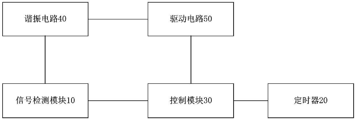
[0026] The electromagnetic heating system includes a resonant circuit composed of a power switch tube, a resonant capacitor and a resonant coil, and a drive circuit for driving the power switch tube to turn on or off. The electromagnetic heating system may also include a power supply ci...


PUM


Abstract

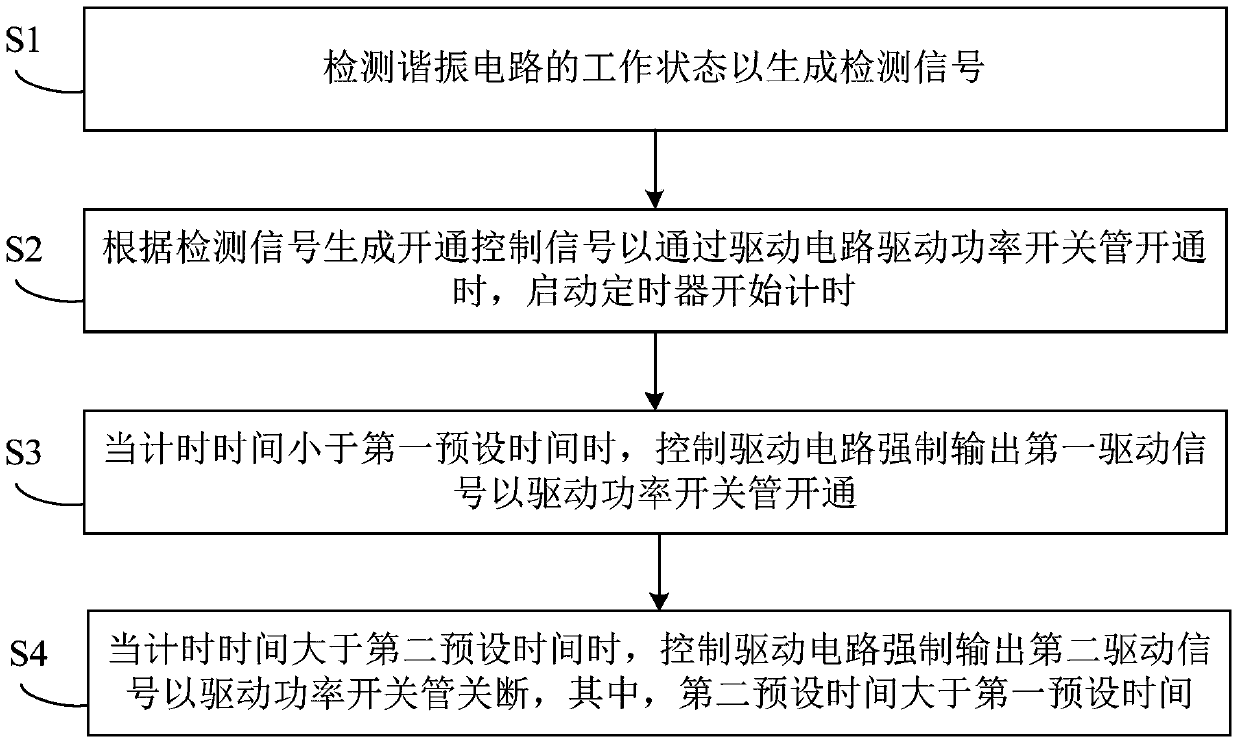
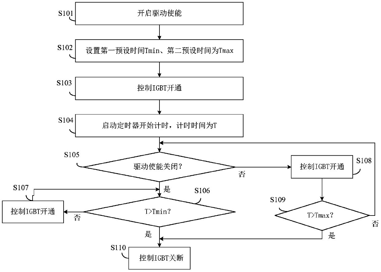
The invention discloses a control method and apparatus for turning-on time of a power switch tube in an electromagnetic heating system. The method comprises: a working state of a resonance circuit is detected to generate a detection signal; according to the detection signal, a turning-on control signal is generated and thus when a power switch tube is driven to be turned on by a drive circuit, a timer is turned on to starting timing; when the timing time is smaller than first preset time, the drive circuit is controlled to output a first drive signal in a forced manner to drive the power switch tube to be turned on, and when the timing time is larger than second preset time, the drive circuit is controlled to output a second drive signal in a forced manner to drive the power switch tube to be turned off, wherein the second preset time is larger than the first preset time. Therefore, the turning-on time of the power switch tube can be limited effectively; problems of high switch losses caused by too short turning-on time of the power switch tube and over-current breakdown caused by too long turning-on time of the power switch tube can be solved; and thus reliability of the power switch tube can be improved.

Description

technical field [0001] The invention relates to the technical field of household appliances, in particular to a method for controlling the turn-on time of a power switch tube in an electromagnetic heating system, a device for controlling the turn-on time of a power switch tube in an electromagnetic heating system, and an electromagnetic heating cooking appliance. Background technique [0002] During the working process of the relevant electromagnetic heating system, too short or too long turn-on time of the power switch tube will bring adverse effects. When the turn-on time of the power switch tube is too short, the switching frequency increases and the switching loss increases, which easily leads to less energy storage in the coil disk at a time, and the resonant circuit cannot oscillate to a low voltage, and the turn-on voltage of the power switch tube is high, the loss is large and it is easy to hit wear; when the power switch tube is turned on for too long, the peak curr...

Claims


Application Information

Patent Timeline
Patent Type & Authority Patents(China)
IPC IPC(8): H05B6/06H05B6/12
Inventor 汪钊陈伟李新峰王云峰麻百忠
Owner FOSHAN SHUNDE MIDEA ELECTRICAL HEATING APPLIANCES MFG CO LTD
Learn More