Vehicle-mounted electronic control device
A vehicle-mounted electronic control and main control circuit technology, applied in the direction of program control, computer control, general control system, etc., can solve the problems of slow downlink communication speed, difficult processing speed, inability to drive and control, etc., and achieve miniaturization and high speed Effects of processing performance and reduction in the number of input terminals
- Summary
- Abstract
- Description
- Claims
- Application Information
AI Technical Summary
Problems solved by technology
Method used
Image
Examples
Embodiment approach 1
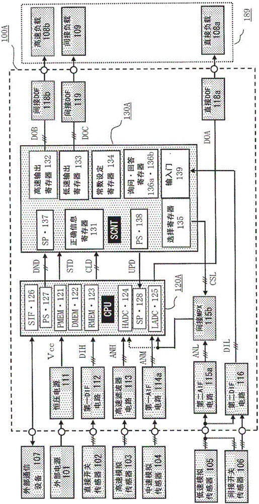
[0041] The overall structural block diagram of the vehicle-mounted electronic control device according to Embodiment 1 of the present invention is figure 1 structure in detail.
[0042] figure 1 Among them, the vehicle-mounted electronic control device 100A includes a main control circuit unit 120A and a dual-purpose control circuit unit 130A. The vehicle-mounted electronic control device 100A is connected to the vehicle-mounted battery, that is, an external power source 101 via a power switch not shown in the figure, and is connected to the external power source 101 via an internal constant-voltage power source 111. To obtain the control voltage Vcc and operate. The plurality of direct switch sensors 102 are, for example, engine crank angle sensors or vehicle speed sensors, and are input in parallel to digital input ports of the main control circuit unit 120A as direct input signals DIH via the first digital input interface circuit 112 . The high-speed analog sensor 103 is,...
Embodiment approach 2
[0141] with figure 1 Focusing on the differences, the overall structural block diagram of the vehicle-mounted electronic control device in Embodiment 2 of the present invention is Figure 7 structure is described. In addition, in each figure, the same reference numerals represent the same or corresponding parts, figure 1 and Figure 7 The main difference is that the main control circuit part 120B is used instead of the main control circuit part 120A, and the dual-purpose control circuit part 130B is used instead of the dual-purpose control circuit part 130A, and the dual-purpose control circuit part 130B is changed from the logic control circuit SCNT to the auxiliary microprocessor SCPPU . In addition, an abnormal information register 134e is added to the dual-purpose control circuit unit 130B, and if abnormal information is stored therein, a read request signal REQ is generated to the main control circuit unit 120B through a dedicated line.
[0142] Figure 7 Among them,...
Embodiment approach 3
[0186] with figure 1 Focusing on the differences, the overall structural block diagram of the vehicle-mounted electronic control device in Embodiment 3 of the present invention is Figure 9 structure in detail.
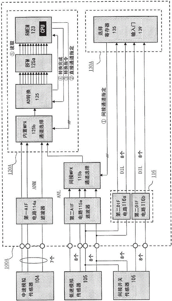
[0187] In addition, in each figure, the same reference numerals represent the same or corresponding parts, figure 1 and Figure 9 The main difference is that the main control circuit unit 120C is used instead of the main control circuit unit 120A, and the dual-purpose control circuit unit 130C is used instead of the dual-purpose control circuit unit 130A. The main control circuit unit 120C only has a high-speed AD converter 124 and does not have Built-in multiplexer 125b (refer to figure 2 ) to select the multi-channel AD converter 125 of the input channel. Therefore, the medium-speed analog input signal ANM and the low-speed analog input signal ANL are input to a specific channel of the high-speed AD converter 124 via the extended indirect multiplexer 145C capab...
PUM
 Abstract
Description
Claims
Application Information
 - R&D
- Intellectual Property
- Life Sciences
- Materials
- Tech Scout
- Unparalleled Data Quality
- Higher Quality Content
- 60% Fewer Hallucinations
Browse by: Latest US Patents, China's latest patents, Technical Efficacy Thesaurus, Application Domain, Technology Topic, Popular Technical Reports.
© 2025 PatSnap. All rights reserved.Legal|Privacy policy|Modern Slavery Act Transparency Statement|Sitemap|About US| Contact US: help@patsnap.com


