Supercharge Your Innovation With Domain-Expert AI Agents!

Slave station apparatus, master station apparatus, optical communication system, and abnormality detection method

An anomaly detection and master station technology, applied in the field of optical communication systems, which can solve problems such as increased failures

Inactive Publication Date: 2017-04-19
MITSUBISHI ELECTRIC CORP
View PDF6 Cites 4 Cited by
  • Summary
  • Abstract
  • Description
  • Claims
  • Application Information

AI Technical Summary

Problems solved by technology

In addition, there is a problem that failures increase due to human error when setting jobs

Method used


Image

  • Slave station apparatus, master station apparatus, optical communication system, and abnormality detection method
  • Slave station apparatus, master station apparatus, optical communication system, and abnormality detection method
  • Slave station apparatus, master station apparatus, optical communication system, and abnormality detection method

Examples


Embodiment approach

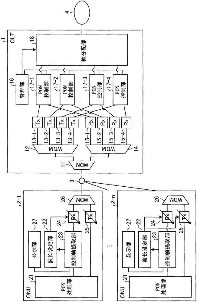
[0024] figure 1 It is a diagram showing a configuration example of the optical communication system of the present invention. In this embodiment, a TWDM-PON system will be described as an example of the optical communication system of the present invention. Such as figure 1 As shown, the optical communication system of this embodiment has: OLT1 as the master station device; ONU2-1~2-n as the slave station device; The separator 3. In addition, n is an integer of 2 or more. In addition, in figure 1 In the figure, an example in which there are a plurality of ONUs constituting the optical communication system is shown, but there may be one ONU constituting the optical communication system. The splitter 3 branches the optical signals received from the OLT1 and outputs them to the optical fibers connected to the ONUs 2-1~2-n respectively, and combines the optical signals received from the ONUs 2-1~2-n to the optical signals connected to the OLT1. Optical output. The OLT1 is c...


PUM


Abstract

An ONU 2-1, which receives an optical signal from an OLT 1 comprising PON control units 17-1 to 17-4, comprises an optical receiver 24 and a control frame extraction unit 23. The optical receiver 24 converts the optical signal, which has an optical wavelength that has been set from among a plurality of optical wavelengths, to an electric signal. The control frame extraction unit 23 extracts and holds wavelength correspondence information received from the OLT 1 and indicating correspondences between the MAC addresses of the PON control units 17-1 to 17-4 and the optical wavelengths. When having received a wavelength change request, the control frame extraction unit 23 extracts an optical wavelength as changed, which is designated by the wavelength change request, and determines, on the basis of the extracted optical wavelength as changed and the wavelength correspondence information, a set address that is the MAC address of the PON control unit to which the ONU 2-1 is to connect after the wavelength change. The control frame extraction unit 23 then determines, on the basis of the MAC address of the transmission source stored in a received control frame and the set address, whether abnormality has occurred or not.

Description

technical field [0001] The present invention relates to optical communication systems using multiple optical wavelengths for optical transmission. Background technique [0002] As one method of accessing the network, there is a PON (Passive Optical Network: Passive Optical Network) system. Due to the increase in data traffic in the access network in recent years, bandwidth is insufficient in the conventional TDM (Time Division Multiplexing: Time Division Multiplexing) type PON system. Therefore, as described in Patent Document 1 and Non-Patent Document 1, a TWDM (Time and Wavelength Division Multiplexing)-PON system is being discussed: the OLT (Optical Line Terminal) has a plurality of ONUs (Optical Network Network Unit) uses the optical wavelength channel to expand the transmission capacity of each ONU by reducing the number of ONUs performing TDM in one optical wavelength channel. [0003] prior art literature [0004] patent documents [0005] Patent Document 1: Japan...

Claims


Application Information

Patent Timeline
Patent Type & Authority Applications(China)
IPC IPC(8): H04L12/44H04L69/40
CPCH04L43/0888H04J14/0256H04J14/0282H04Q2011/0064H04Q11/0067H04Q2011/0083Y04S40/00H04J14/02122H04J14/0212H04L41/0668H04L41/069H04Q2011/0016
Inventor 向井宏明西谷隆志
Owner MITSUBISHI ELECTRIC CORP
Features
  • R&D
  • Intellectual Property
  • Life Sciences
  • Materials
  • Tech Scout
  • Unparalleled Data Quality
  • Higher Quality Content
  • 60% Fewer Hallucinations
Learn More