Metal ultra-thin strip rolling mill with selectable driving modes and rolling method thereof

A transmission method and metal pole technology, applied in the direction of metal rolling, metal rolling, metal rolling racks, etc., can solve the problems of high technical threshold and risk, large investment, high purchase, operation and maintenance costs

Active Publication Date: 2017-04-26
NORTHEASTERN UNIV
View PDF6 Cites 6 Cited by
  • Summary
  • Abstract
  • Description
  • Claims
  • Application Information

AI Technical Summary

Problems solved by technology

[0003] The ultra-thin strips of metals, alloys and metal-based composite materials are mostly obtained by rolling, and the rolling mills used are mostly multi-roll mills, and the multi-roll mills have complex structures, high technical thresholds and risks, and high purchase, operation and maintenance costs. Large investment will increase the financial cost of the enterprise

Method used


Image

  • Metal ultra-thin strip rolling mill with selectable driving modes and rolling method thereof
  • Metal ultra-thin strip rolling mill with selectable driving modes and rolling method thereof
  • Metal ultra-thin strip rolling mill with selectable driving modes and rolling method thereof

Examples


Embodiment 1

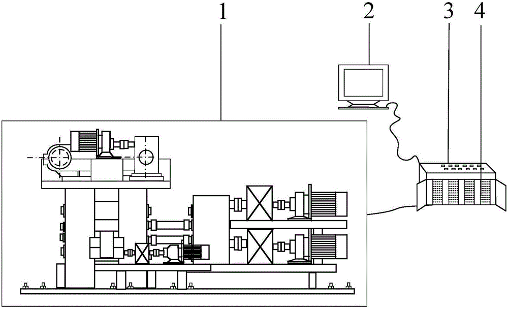
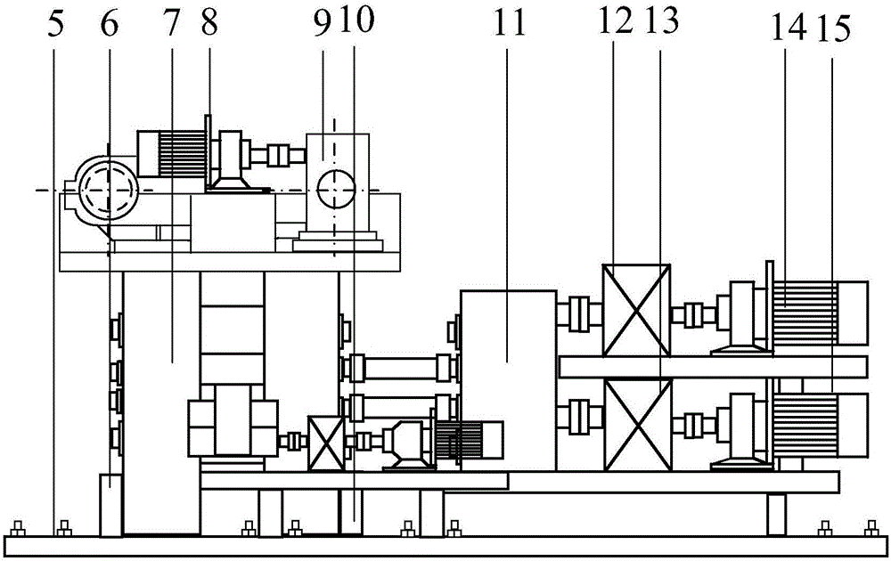
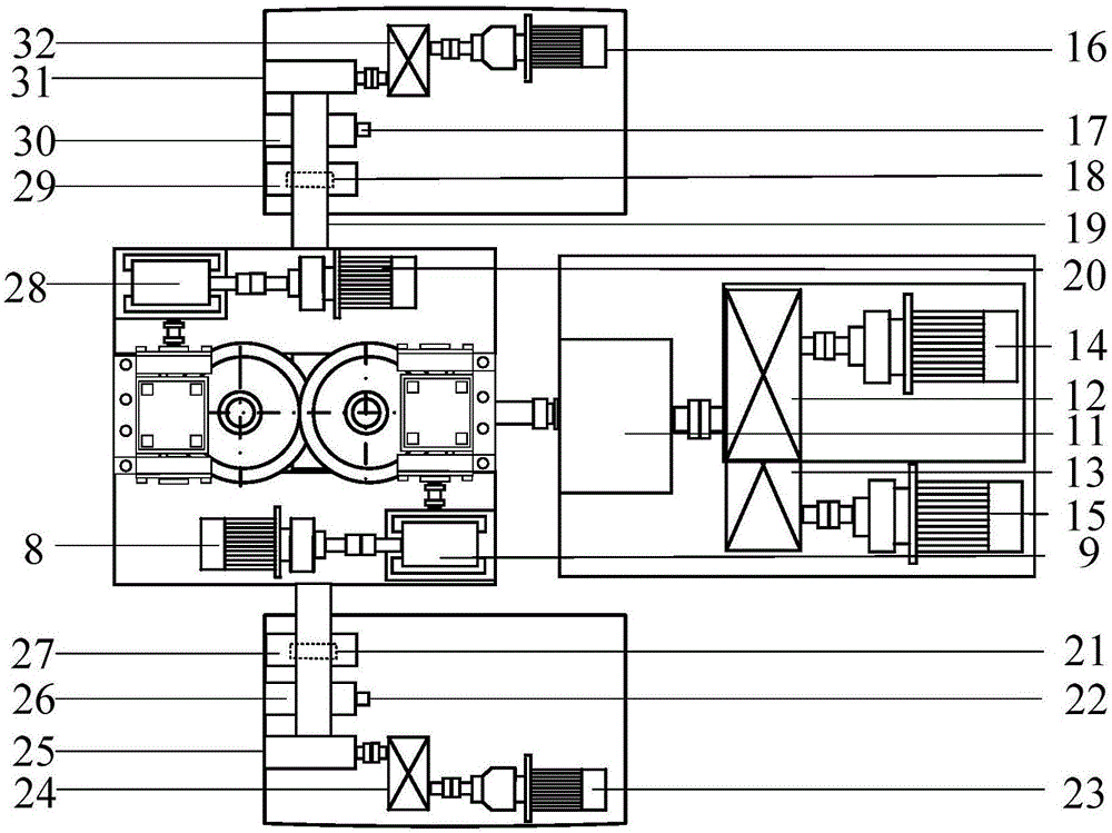
[0054] The structure of the metal ultra-thin strip mill with optional transmission mode is as follows figure 1 , 2 As shown in and 3, the transmission principle of the work roll transmission mode is as follows Figure 4 As shown, the transmission principle of the supporting roller transmission method is as follows Figure 5 As shown, the transmission principle of the compound gearbox is as follows Image 6 with 7 As shown, the sectional structure of the transmission part of the compound gearbox is as Figure 8 As shown, it includes a rolling mill mechanical part 1 and a control system. The rolling mill mechanical part 1 includes a base 5, an arch 7, a first main drive motor 14, a second main drive motor 15, a first main reducer 12, and a second main reducer Machine 13, upper work roll 34, lower work roll 35, upper support roll 33, lower support roll 36, compound gear box 11, pressing device, balance device, roll changing device, first tension motor 23, second tension motor 16 ,...

Embodiment 2

[0077] The device structure is the same as in Example 1;

[0078] The rolling method using the above device is: the rolled piece is 201 stainless steel, the initial thickness is 0.3mm, the width is 300mm, the diameter of the upper and lower work rolls is 120mm, the upper and lower support rolls The diameter is 400mm, the target thickness of the rolled piece is 30μm, and the work roll transmission mode is adopted:

[0079] 1. Use universal joints to connect the upper work roll corresponding output shaft 40 and the lower work roll corresponding output shaft 41 of the composite gear box 11 to the upper work roll 34 and the lower work roll 35 respectively;

[0080] 2. Put the rolled piece in a roll on a drum, and wind one end of the rolled piece through the gap between the upper work roll 34 and the lower work roll 35 on the other side of the drum;

[0081] 3. Start the power supply of the ultra-thin strip rolling mill, set the speed of the upper work roll 34 and the lower work roll 35 to...


PUM


Abstract

The invention provides a metal ultra-thin strip four-roller rolling mill with selectable driving modes and a rolling method thereof. The rolling mill comprises a rolling mill mechanical part and a control system, wherein two main driving motors, two main reduction gears and a compound gear box are positioned on the same side of a mill housing; the compound gear box is provided with four output shafts which are connected with an upper support roller and a lower support roller through universal spindles or connected with an upper work roller and a lower work roller through the universal spindles; and the upper driving part and the lower driving part of the compound gear box are independently controlled by the first main driving motor and the second main driving motor respectively and are mutually independent, and the reduction ratio of the upper driving part to the lower driving part is adjustable. The rolling method has a support roller driving mode and a work roller driving mode. When the rolling mill is used for asymmetrical rolling of ultra-thin strips, as asymmetrical rolling can break through the restriction from the minimum rollable thickness of synchronous rolling, the sheet rolling capacity is higher, the on-line adjustment range of the different speed ratio is broad, and the range of rollable raw materials can be effectively expanded.

Description

Technical field [0001] The invention belongs to the technical field of metal rolling, and particularly relates to a metal ultra-thin strip rolling mill with optional transmission mode and a rolling method thereof. Background technique [0002] In recent years, micro-manufacturing technology and micro-forming technology have developed rapidly, and the demand for ultra-thin strips of metals, alloys and metal matrix composites is increasing. These ultra-thin strips are widely used in the microelectronics industry, micro-manufacturing industry, and instrumentation industry. And micro-electromechanical industry, etc. [0003] Ultra-thin strips of metals, alloys and metal-based composite materials are mostly obtained by rolling, and the rolling mills used are mostly multi-roll mills, which have complex structures, high technical barriers and high risks, and high purchase, operation and maintenance costs. Large investments have increased the financial costs of enterprises. Summary of th...

Claims


Application Information

Patent Timeline
Patent Type & Authority Applications(China)
IPC IPC(8): B21B1/40B21B35/00B21B35/12B21B35/14B21B38/00B21B13/02B21B31/20
CPCB21B1/40B21B13/02B21B31/20B21B35/00B21B35/12B21B35/14B21B38/00B21B2013/025B21B2275/04
Inventor 刘相华孙祥坤陈敬琪徐梓淦宋孟赵启林
Owner NORTHEASTERN UNIV
Why Eureka
Try Eureka