The installation structure and construction method of the temporary waterproof device when the shield reaches the non-main structure

A technology of main structure and waterproof device, applied in vertical shaft equipment, earthwork drilling, wellbore lining, etc., can solve problems such as affecting construction efficiency, prolonging construction progress and construction period, prolonging process conversion time, etc., so as to improve construction efficiency and shorten the The construction progress and construction period, the effect of saving process conversion time

Active Publication Date: 2018-10-23
CHINA RAILWAY TUNNEL GROUP CO LTD +1
View PDF10 Cites 0 Cited by
  • Summary
  • Abstract
  • Description
  • Claims
  • Application Information

AI Technical Summary

Problems solved by technology

However, there are few domestic researches on this aspect, and it is impossible to solve the shield machine stoppage caused by the late construction of the station structure during the construction process, which prolongs the process changeover time, thereby affecting the construction efficiency and prolonging the construction progress and construction period.

Method used


Image

  • The installation structure and construction method of the temporary waterproof device when the shield reaches the non-main structure
  • The installation structure and construction method of the temporary waterproof device when the shield reaches the non-main structure
  • The installation structure and construction method of the temporary waterproof device when the shield reaches the non-main structure

Examples


example 1

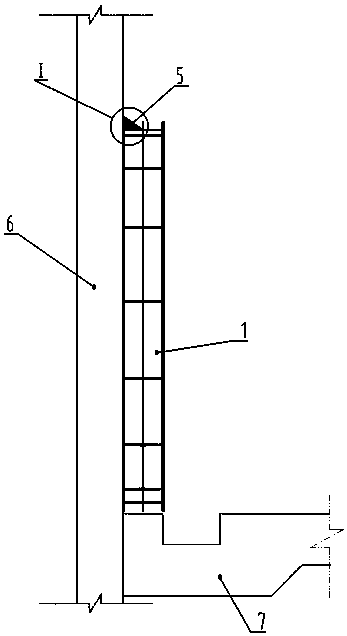
[0037] see Figure 1-2 , in the figure, the shield of the present invention reaches the temporary waterproof device installation structure without a main structure, including a connecting steel ring 1, double rows of steel bars 2, steel mesh 3, and concrete 5.

[0038] Wherein, the connecting steel ring is located on the ground connection wall 6 and matches with the set hole. The double rows of steel bars are arranged on the outside of the connecting steel ring in a circular direction, and are implanted in the ground connection wall, and the implanted double rows of steel bars and the connecting steel ring are coaxially arranged. The outer protruding end connecting the steel ring and the double row of steel bars is welded and fixed. The steel mesh is bound on the external extension of the double row of steel bars, and C30 concrete is molded to seal the gap between the steel ring and the ground wall. The row spacing of the double-row steel bars is 30cm, the circumferential sp...

Embodiment 2

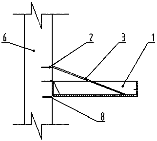
[0051] see figure 2 , the structure of this embodiment is similar to that of Embodiment 1, and the same parts of the structure will not be repeated here. The difference is that this embodiment also includes a full-circle cutout hole 8 inside the door that is located on the inner side of the connecting steel ring, and the cutout hole The depth is consistent with the depth of the planted reinforcement, which is used to reduce the disturbance of the connection position of the steel ring when the shield tunneling tool cuts the door.

[0052] The specific construction steps 1 to 4 of this embodiment are described in Embodiment 1, and will not be repeated here. The difference is that it also includes step 5, drilling the entire ring inside the door:

[0053]The full-ring resection of the portal is carried out on the inner side of the connecting steel ring, and the depth of the resection is consistent with the depth of the reinforcement, so as to reduce the disturbance of the connec...


PUM


Abstract

The invention belongs to the technical field of shield arrival construction, and particularly relates to an installing structure for a shield arrival temporary waterproof device without a main structure and a construction method of the installing structure. The installing structure comprises a connecting steel ring which is located on a diaphragm wall and matched with a tunnel portal. Two rows of circumferential steel bars are embedded in the portion, outside the connecting steel ring, of the diaphragm wall. The embedded two rows of circumferential steel bars are arranged coaxial with the connecting steel ring, and the outer stretching-out ends of the two rows of steel bars are fixed to the connecting steel ring; and meanwhile, steel bar meshes are fixed to the outer stretching-out ends of the two rows of steel bars. Concrete is poured between the steel bar meshes and the connecting steel ring as well as between the steel bar meshes and the diaphragm wall so as to seal clearances between the connecting steel ring and the diaphragm wall. The construction method sequentially comprises the steps of machining of the connecting steel ring, embedding of the steel bars on the tunnel portal, positioning and fixing of the connecting steel ring, C30 formwork-building concrete construction on the peripheries of steel ring plates and the like. By adoption of the installing structure for the shield arrival temporary waterproof device without the main structure and the construction method of the installing structure, shield halt caused by late construction of a station structure in the construction process can be effectively prevented, the process conversion time is reduced, the construction efficiency is improved, the construction progress is accelerated, and the construction period is shortened.

Description

technical field [0001] The invention belongs to the technical field of shield tunneling construction, and in particular relates to a temporary waterproof device installation structure for a shield tunneling without a main body structure and a construction method thereof. Background technique [0002] Due to the mismatch between the station construction and the construction progress of the shield section, the conflict between the station construction and the arrival time of the shield, the side wall of the main structure was not constructed when the shield arrived, and the temporary waterproof device installed on the main structure could not be installed. After the construction of the base plate of the station is completed, the shield tunneling operation will be carried out. It is necessary to install a temporary waterproof device on the continuous wall to connect the steel ring. However, there are few researches in this area in China, and it is impossible to solve the shield...

Claims


Application Information

Patent Timeline
Patent Type & Authority Patents(China)
IPC IPC(8): E21D11/38E21D11/10
CPCE21D11/107E21D11/38
Inventor 何列贺婷薛景沛郭卫社陈树茂方一航侯文凯楚明泰石立新
Owner CHINA RAILWAY TUNNEL GROUP CO LTD
Why Eureka
Try Eureka