Air leakage control system of air preheater

An air preheater and control system technology, which is applied in the directions of combustion air/fuel supply, non-flammable liquid/gas transportation, heat exchange equipment, etc., can solve the problems of low control accuracy, easy damage, and inability to maintain online Achieve the effect of improving control efficiency and solving low control accuracy

Inactive Publication Date: 2017-04-26
HUANENG CLEAN ENERGY RES INST
View PDF7 Cites 4 Cited by
  • Summary
  • Abstract
  • Description
  • Claims
  • Application Information

AI Technical Summary

Problems solved by technology

[0005] An embodiment of the present invention provides an air leakage control system for an air preheater, to at least solve the technical proble

Method used


Image

  • Air leakage control system of air preheater
  • Air leakage control system of air preheater
  • Air leakage control system of air preheater

Examples


Embodiment 1

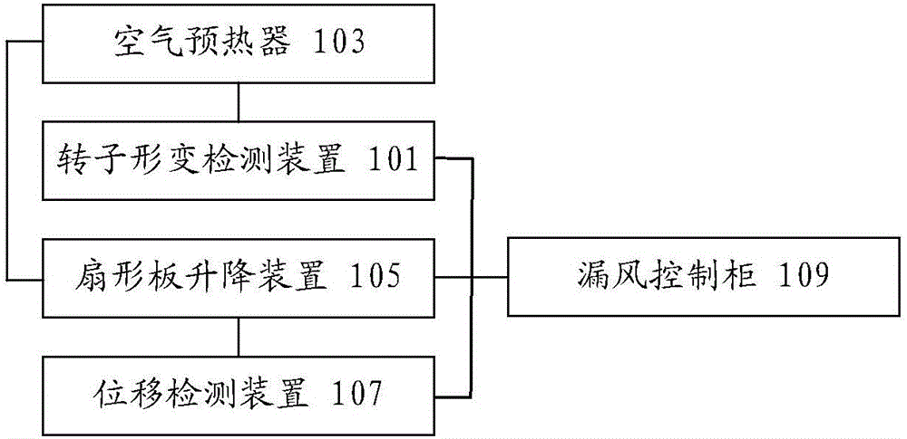
[0024] According to an embodiment of the present invention, an embodiment of an air leakage control system for an air preheater is provided, figure 1 It is a structural schematic diagram of an optional air leakage control system of an air preheater according to an embodiment of the present invention, as shown in figure 1 As shown, the air leakage control system of the air preheater includes:

[0025] The rotor deformation detection device 101 is connected with the air preheater 103 and is used to detect the deformation of the rotor of the air preheater; the sector plate lifting device 105 is connected with the air preheater 103 and is used for adjusting The fan-shaped plate is lifted and lowered; the displacement detection device 107 is connected with the fan-shaped plate lifting device 105, and is used to detect the downward displacement of the fan-shaped plate; the air leakage control cabinet 109 is connected with the rotor deformation detection device 101, the fan-shaped pl...

Embodiment 2

[0048] According to an embodiment of the present invention, an embodiment of an air leakage control method for an air preheater is provided. It should be noted that the steps shown in the flow chart of the accompanying drawings can be implemented in a computer system such as a set of computer-executable instructions and, although a logical order is shown in the flowcharts, in some cases the steps shown or described may be performed in an order different from that shown or described herein.

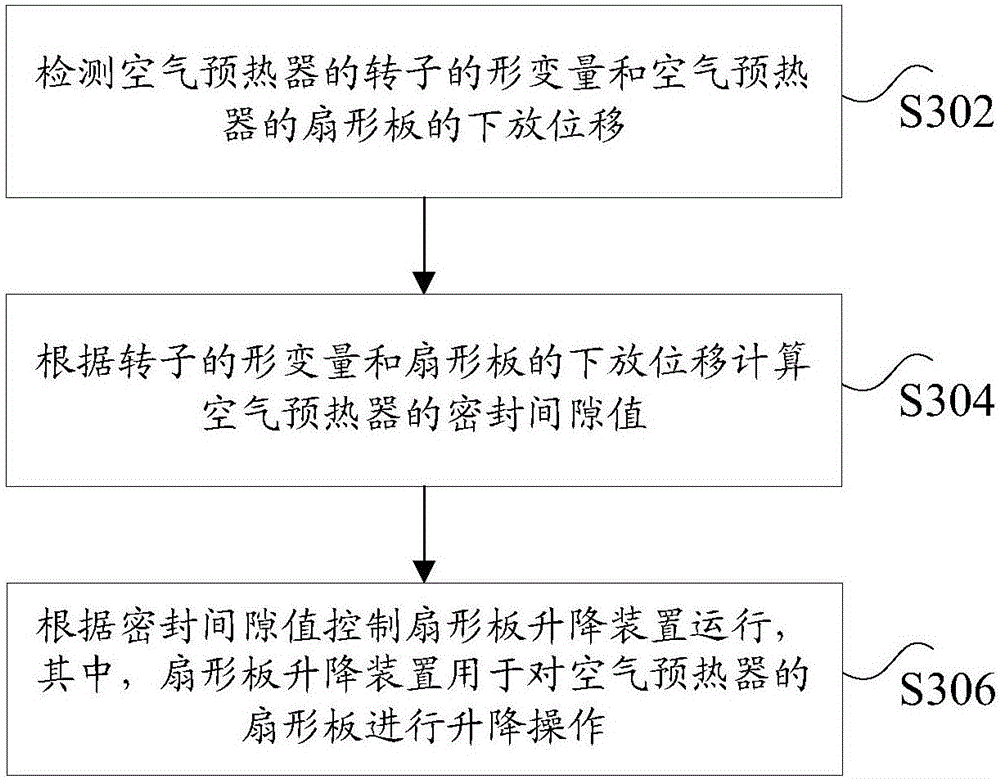
[0049] image 3 is a schematic flow chart of an air leakage control method for an air preheater according to an embodiment of the present invention, as shown in image 3 As shown, the method includes the following steps:

[0050] Step S302, detecting the deformation of the rotor of the air preheater and the lowering displacement of the sector plates of the air preheater;

[0051] Step S304, calculating the sealing gap value of the air preheater according to the deformation of the rotor a...


PUM


Abstract

The invention discloses an air leakage control system of an air preheater. The system comprises a rotor deformation detecting device connected with the air preheater and used for detecting the deformation amount of a rotor of the air preheater, a sector plate lifting device connected with the air preheater and used for conducting lifting operation on a sector plate of the air preheater, a displacement detecting device connected with the sector plate lifting device and used for detecting decreasing displacement of the sector plate, and an air leakage control cabinet connected with the rotor deformation detecting device, the sector plate lifting device and the displacement detecting device and used for obtaining a sealing clearance value of the air preheater through the deformation amount of the rotor and the decreasing displacement of the sector plate and controlling the sector plate lifting device to operate according to the sealing clearance value. The technical problems that in the prior art, air leakage control systems of air preheaters are low in control precision and liable to be damaged and cannot be maintained online are solved.

Description

technical field [0001] The invention relates to the field of automatic control, in particular to an air leakage control system of an air preheater. Background technique [0002] Rotary air preheaters are widely used in large thermal power plants and are important components for reducing coal consumption and improving boiler thermal efficiency. However, the rotor of the rotary air preheater generally has air leakage due to the existence of "mushroom-shaped" thermal deformation. The air leakage will not only increase the heat loss of the smoke exhaust and the power consumption of the induced draft fan, but also accelerate the corrosion of the heating surface due to the decrease of the smoke temperature. When the air leakage is serious, the amount of air sent to the boiler for combustion will be insufficient, which will directly affect the output of the boiler. [0003] The air leakage control system is a set of automatic tracking control system designed to solve the air leak...

Claims


Application Information

Patent Timeline
IPC IPC(8): F23L15/00F28F27/00
CPCF23L15/00F23L2900/15043F28F27/00Y02E20/34
Inventor 马铭远徐越郑建涛
Owner HUANENG CLEAN ENERGY RES INST
Why Eureka
Try Eureka