Heat exchange copper tube provided with straight internal threads

A heat exchange copper tube and internal thread technology, which is applied to tubular elements, heat transfer modification, heat exchange equipment, etc., can solve the problems of small flow resistance, heat exchange area, flow dead zone of spiral grooves, and large flow resistance of threaded pipes. , to increase the degree of fluid turbulence, reduce the flow resistance, and increase the contact area.

Active Publication Date: 2017-04-26
ZHEJIANG NAILE COPPER +1
View PDF9 Cites 4 Cited by
  • Summary
  • Abstract
  • Description
  • Claims
  • Application Information

AI Technical Summary

Problems solved by technology

[0008] Aiming at the problems that the tooth lines of the existing straight inner toothed tube and threaded pipe are easily damaged during the tube expansion process, and the flow resistance of the threaded pipe is large, there is a flow dead zone in the spiral groove, and the heat exchange area of ​​the straight inner toothed tube is small, etc., The purpose of the present invention is to provide a heat exchange copper tube with low flow resistance and large heat exchange area, which is not easy to be damaged in the process of expanding the tube.

Method used


Image

  • Heat exchange copper tube provided with straight internal threads
  • Heat exchange copper tube provided with straight internal threads
  • Heat exchange copper tube provided with straight internal threads

Examples


Embodiment Construction

[0029] The specific embodiment of the present invention will be further described below in conjunction with accompanying drawing:

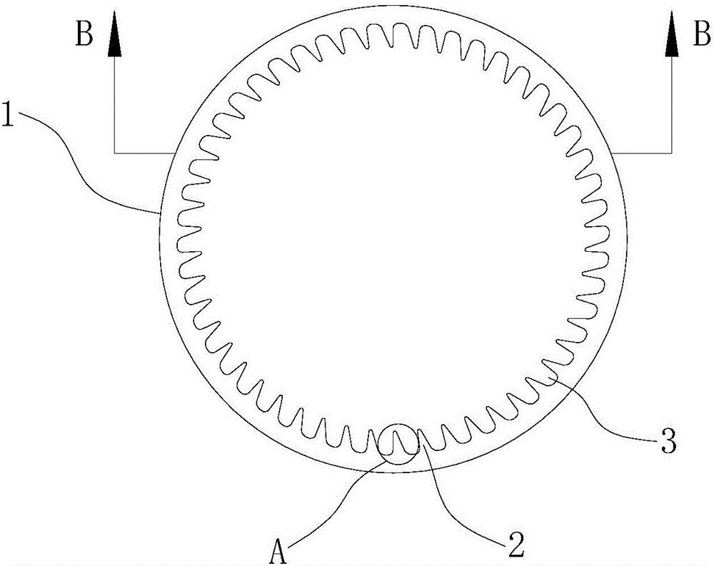
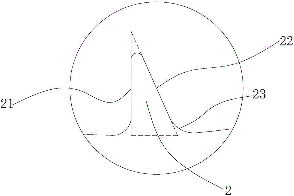
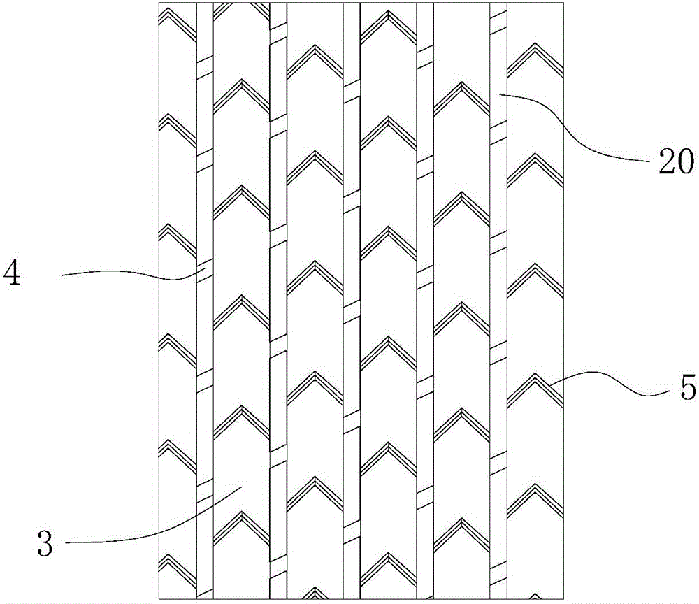
[0030] Such as figure 1 , figure 2 , image 3 As shown, a straight internal thread heat exchange copper tube includes a copper tube body 1, a number of evenly distributed right-angle teeth 2 are arranged on the inner surface of the copper tube body along the circumferential direction, and the two sides of the right-angle teeth are respectively a straight side and a The hypotenuse, wherein the extension line of the straight side crosses the center of the cross-section of the copper tube body to form a supporting straight side 21, the hypotenuse and the straight side intersect in a circular arc transition at the top of the right-angle tooth, the hypotenuse forms an expanded hypotenuse 22, and the tooth of the right-angle tooth The apex angle is 30°-45°, preferably 45°. In this way, during the tube expansion process, the expansion tube squeezes a...


PUM

PropertyMeasurementUnit
angleaaaaaaaaaa
angleaaaaaaaaaa

Abstract

The invention relates to the technical field of heat exchange copper tubes and particularly discloses a heat exchange copper tube provided with straight internal threads. The heat exchange copper tube provided with the straight internal threads comprises a copper tube body. A plurality of right-angled teeth are arranged on the inner side of the copper tube body in the circumferential direction. The two side edges of each right-angled tooth are a supporting straight edge and an expanding bevel edge intersecting with the supporting straight edge, wherein the extension line of the supporting straight edge passes through the center of the circle of the copper tube, the supporting straight edge is connected with the expanding bevel edge in a circular arc transmission on the top of the right-angled tooth. The addendum angle of each right-angled tooth is 45 degrees. The right-angled teeth are stretched along the axis of the copper tube to form straight racks. A straight tooth groove is formed between every two adjacent straight racks. A spiral guide groove penetrating the straight racks is formed in the copper tube body. The spiral guide groove extends from one end of the copper tube body to the other end of the copper tube body. A turbulence tooth group is further arranged on the inner side of the copper tube body, and the turbulence tooth group and the spiral guide groove extend in a double-helix shape. The turbulence tooth group comprises a plurality of turbulence tooth teeth located in the straight tooth grooves. By the adoption of the heat exchange copper tube provided with the straight internal threads, tooth patterns can be prevented from being damaged in the tube expanding process, the flowing resistance is reduced, the flowing turbulence degree is increased, the heat exchange efficiency is improved, and the heat exchange copper tube provided with the straight internal threads is convenient to machine.

Description

technical field [0001] The invention relates to the technical field of heat-exchanging copper tubes, in particular to a heat-exchanging copper tube with a straight rack on the inner wall. Background technique [0002] The heat exchange copper tubes used in air-conditioning heat exchangers generally have smooth tubes and non-smooth tubes. The inner side of the smooth tube is smooth, and the inner side of the non-smooth tube is also called a threaded tube because of the helical thread. Compared with smooth tubes, threaded tubes have higher heat transfer efficiency due to the existence of threads, larger heat transfer area, and higher disturbance degree of gas-liquid interface, and are therefore used by more and more air-conditioning companies. However, the use of threaded pipes has the following disadvantages: [0003] 1. The heat exchange tube needs to be expanded through the expansion tube, so that the top of the thread is destroyed by the radial extrusion of the expansion ...

Claims


Application Information

Patent Timeline
Patent Type & Authority Applications(China)
IPC IPC(8): F28F1/40F28F13/18F28F19/02
CPCF28F1/40F28F13/18F28F19/02
Inventor 刘晋龙
Owner ZHEJIANG NAILE COPPER
Why Eureka
Try Eureka