
Radar object positioning method based on machine learning

A radar target and positioning method technology, applied in the field of signal processing, can solve problems such as complex calculations, system error accumulation, and weak portability

Active Publication Date: 2017-04-26
CHINA ACADEMY OF SPACE TECHNOLOGY
View PDF5 Cites 9 Cited by
  • Summary
  • Abstract
  • Description
  • Claims
  • Application Information

AI Technical Summary

Problems solved by technology

[0002] Existing radar systems are based on relatively strict theoretical models and traditional signal processing methods, which mainly have the following problems: (1) It is difficult to model complex environments, system errors accumulate, and high robustness is difficult to achieve; (2) Linear periodic processing methods (such as Fourier transform, etc.), deblurring (range ambiguity, Doppler ambiguity, phase ambiguity, velocity ambiguity, etc.) requires complex calculations and expensive hardware costs; (3) The radar system is complex, poor in versatility, and weak in portability , long upgrade cycle

Method used


Image

  • Radar object positioning method based on machine learning
  • Radar object positioning method based on machine learning
  • Radar object positioning method based on machine learning

Examples


Embodiment Construction

[0038] The application will be further described in detail below in conjunction with the accompanying drawings and embodiments. It should be understood that the specific embodiments described here are only used to explain related inventions, rather than to limit the invention. It should also be noted that, for the convenience of description, only the parts related to the related invention are shown in the drawings.

[0039] It should be noted that, in the case of no conflict, the embodiments in the present application and the features in the embodiments can be combined with each other. The present application will be described in detail below with reference to the accompanying drawings and embodiments.

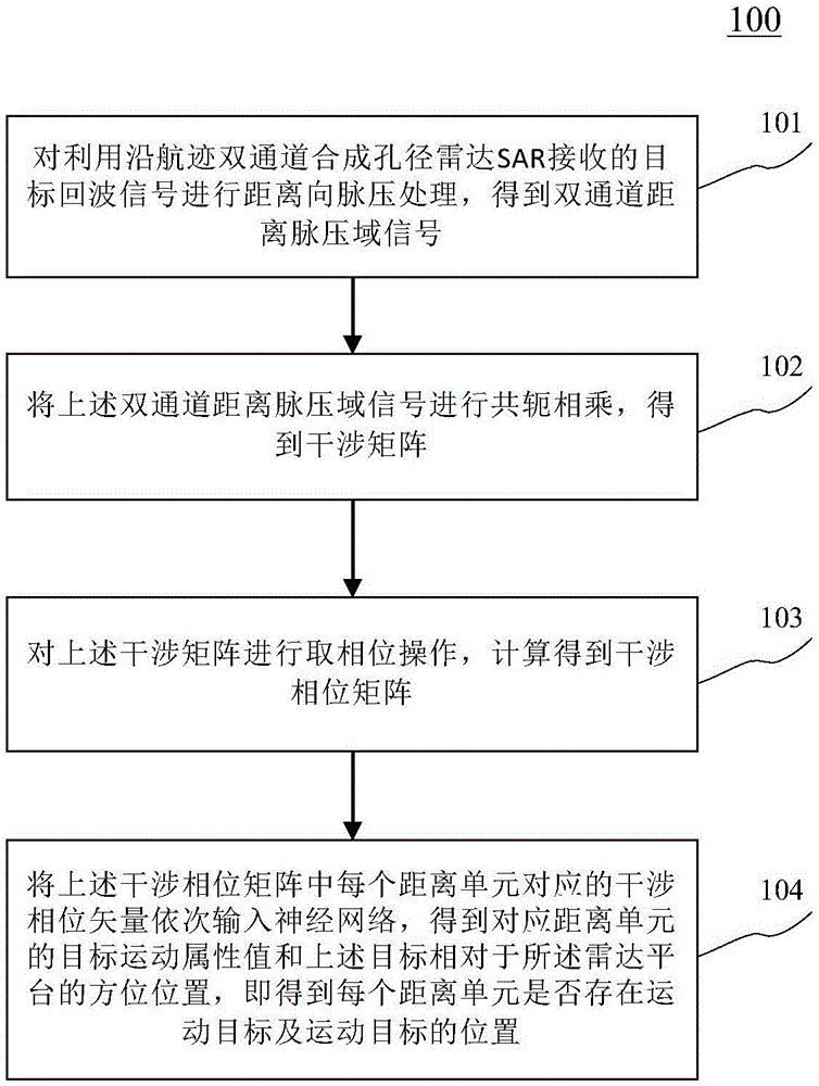
[0040] figure 1 A flowchart 100 of an embodiment of the machine learning-based radar target location method of the present application is shown. The radar target localization method based on machine learning comprises the following steps:

[0041] Step 101 , performing ran...


PUM


Abstract

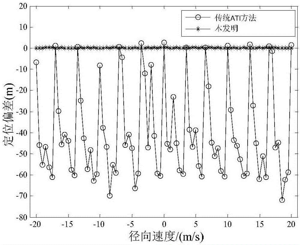
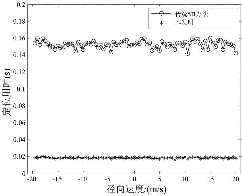
The invention proposes a radar object positioning method based on machine learning. According to one embodiment of the invention, the method comprises the steps: carrying out the range-direction pulse compression of a target echo signal received by an along-track two-channel SAR (synthetic aperture radar), obtaining an interference phase matrix, sequentially inputting the interference phase vectors corresponding to all distance units in the interference phase matrix into a neural network, and obtaining a result of judgment whether each distance unit has a moving object or not and the orientation position x0 of the moving object. According to the embodiment of the invention, the method avoids problems of complex orientation pulse compression, radial speed estimation and faced phase fuzziness of a conventional ATI (along-track interference) method, thereby solving a problem that the positioning precision of the moving object is decreased because of error accumulation in the above process. The method is higher in positioning precision of the moving object, is lower in time consumption, and can meet the demands of high instantaneity and high positioning precision.

Description

technical field [0001] The present application relates to the field of signal processing technology, specifically to the field of radar target detection and recognition, and in particular to a machine learning-based radar target positioning method, which can be used for radar moving target detection, moving target positioning and tracking, etc. Background technique [0002] Existing radar systems are based on relatively strict theoretical models and traditional signal processing methods, which mainly have the following problems: (1) It is difficult to model complex environments, system errors accumulate, and high robustness is difficult to achieve; (2) Linear periodic processing methods (such as Fourier transform, etc.), deblurring (range ambiguity, Doppler ambiguity, phase ambiguity, velocity ambiguity, etc.) requires complex calculations and expensive hardware costs; (3) The radar system is complex, poor in versatility, and weak in portability , The upgrade cycle is long. ...

Claims


Application Information

Patent Timeline
IPC IPC(8): G01S13/06
CPCG01S13/06
Inventor 张学攀刘波贺杨
Owner CHINA ACADEMY OF SPACE TECHNOLOGY
Learn More