Fluorescence interference microscopic measurement method and device based on stimulated radiation
What is Al technical title?
Al technical title is built by PatSnap Al team. It summarizes the technical point description of the patent document.
A technology of interference microscopy and stimulated radiation, applied in measurement devices, optical devices, instruments, etc., can solve the problems of difficulty in returning probe light, and the detection system cannot achieve high NA and high slope surface detection.
Inactive Publication Date: 2015-09-23
HARBIN INST OF TECH
View PDF5 Cites 0 Cited by
Summary
Abstract
Description
Claims
Application Information
AI Technical Summary
This helps you quickly interpret patents by identifying the three key elements:
Problems solved by technology
Method used
Benefits of technology
Problems solved by technology
[0010] In order to solve the problem that it is difficult for the detection light to return to the detection system and thus cannot achieve high NA and high slope surface detection, the present invention discloses a fluorescence interference microscopic measurement method and device based on stimulated radiation
Method used
Image
Click on the blue label to locate the original text in one second.
Reading with bidirectional positioning of images and text.
Examples
Embodiment Construction
[0022] The specific embodiments of the present invention will be further described in detail below in conjunction with the accompanying drawings.
[0023] The fluorescence interference microscopic measurement method based on stimulated radiation of the present embodiment comprises the following steps:
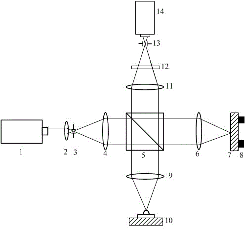
[0024] a, adopt the multi-source organic molecular beam deposition OMBD system, adopt the same process to vapor-deposit the organic thin film, vapor-deposit the same kind of fluorescent organic thin film with the same thickness on the surface of the test piece 10 and the reference mirror 7, and the test piece 10 The surface is changed from the original smooth surface to the diffuse surface;
[0025] b. The measured surface 10 and the reference mirror 7 are excited by the monochromatic detection laser, and the surface radiates quasi-monochromatic light with the same central wavelength and the same spectral width range. The central wavelength of the quasi-monochromatic light is 6...
PUM
Abstract
The invention belongs to the technical field of surface topography measurement, and discloses a method and a device for fluorescence interference microscopic measurement based on stimulated radiation. The method includes: firstly, coating surfaces of a measured piece and a reference mirror; secondly, subjecting the measured piece and the reference mirror to stimulation of monochrome detection laser; and finally, resolving interference fringes on a detection surface. The device a laser device, a converging objective lens, a first pinhole, a collimation and beam expanding objective lens, a beam splitting prism, a reference focusing objective lens, the reference mirror, a displacement driver, a detection focusing objective lens, the measured piece, an imaging converging objective lens, a narrow-band filter, a second pinhole and a detector, wherein the converging objective lens, the first pinhole, the collimation and beam expanding objective lens, the beam splitting prism, the reference focusing objective lens, the reference mirror and the displacement driver are disposed on a direct light path of the laser device along a light transmitting direction, the detection focusing objective lens and the measured piece are disposed on a reflected light path of the beam splitting prism, and the imaging converging objective lens, the narrow-band filter, the second pinhole and the detector are disposed on a transmission light path of the beam splitting prism. By the design that surfaces of the measured piece and the reference mirror are coated by the aid of a vacuum evaporation coating method, measurement light is guaranteed to be capable of returning to a detection system after being reflected by a measured surface, high-NA(numerical aperture) and high-slope surface detection is achieved, and the device is applicable to ultra-precise measurement of three-dimensional topographies of high-NA and high-slope spherical surfaces, aspheric surfaces and free-form surfaces.
Description
technical field [0001] The fluorescence interference microscopic measurement method and device based on stimulated radiation belong to the field of surface topography measurement technology, in particular to a three-dimensional microstructure, microstep, and microgroove used in microstructured optical elements, microstructured mechanical elements, and integrated circuit elements. Ultra-precise, dynamic, high-speed interferometry method and device for groove line width and large numerical aperture optical element surface shape measurement. Background technique [0002] Microscopic interferometry is to use the principle of light wave interference and microscopic magnification for surface measurement. With the rapid development of optoelectronic technology and computer technology, the phase shift technology that directly measures the interferometric phase distribution has been developed in the field of interferometry. The principle is: introduce a time modulation to the phas...
Claims
Application Information
Patent Timeline
Application Date:The date an application was filed.
Publication Date:The date a patent or application was officially published.
First Publication Date:The earliest publication date of a patent with the same application number.
Issue Date:Publication date of the patent grant document.
PCT Entry Date:The Entry date of PCT National Phase.
Estimated Expiry Date:The statutory expiry date of a patent right according to the Patent Law, and it is the longest term of protection that the patent right can achieve without the termination of the patent right due to other reasons(Term extension factor has been taken into account ).
Invalid Date:Actual expiry date is based on effective date or publication date of legal transaction data of invalid patent.