Agile satellite target decomposition method and system based on push-scan trajectories

A target decomposition and trajectory technology, applied in the field of satellite imaging, can solve the problem of not considering the change of satellite attitude and width, and achieve the effect of improving the utilization rate

Active Publication Date: 2017-04-26
NAT UNIV OF DEFENSE TECH
View PDF10 Cites 12 Cited by
  • Summary
  • Abstract
  • Description
  • Claims
  • Application Information

AI Technical Summary

Problems solved by technology

[0004] A typical example of the decomposition using a predefined reference system is that France uses a grid reference system (Grid Reference System, GRS) decomposition method in the imaging mission planning of an Earth observation satellite system. It is more suitable for frame-and-width imaging satellites. For satellites that rely on array detector push-broom imaging, the decomposition of the target is generally realized in the form of strips. This decomposition method is based on the two parameters of direction and offset. The band realizes the decomposition of non-equal-length strips in irregular areas, but this decomposition method does not consider the width change caused by the satellite attitude

Method used


Image

  • Agile satellite target decomposition method and system based on push-scan trajectories
  • Agile satellite target decomposition method and system based on push-scan trajectories
  • Agile satellite target decomposition method and system based on push-scan trajectories

Examples


Embodiment Construction

[0060] The following will clearly and completely describe the technical solutions in the embodiments of the present invention with reference to the accompanying drawings in the embodiments of the present invention. Obviously, the described embodiments are only some, not all, embodiments of the present invention. Based on the embodiments of the present invention, all other embodiments obtained by persons of ordinary skill in the art without making creative efforts belong to the protection scope of the present invention.

[0061] In order to make the above objects, features and advantages of the present invention more comprehensible, the present invention will be further described in detail below in conjunction with the accompanying drawings and specific embodiments.

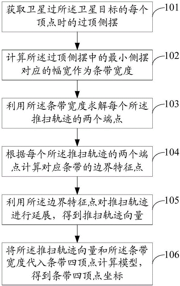
[0062] figure 1 It is a method flowchart of an embodiment of the satellite target decomposition method based on the push-broom trajectory of the present invention;

[0063] see figure 1 , the satellite target de...


PUM


Abstract

The invention discloses a satellite target decomposition method and system based on a push-scan trajectories. The method includes obtaining vertex-crossing side sway of a satellite when crossing each vertex of a satellite target, and calculating breadth corresponding minimum side sway of the vertex-crossing side sway as strip width; utilizing the strip width to solve two endpoints of each push-scan trajectory; calculating boundary feature points of a corresponding strip according to the two endpoints of each push-scan trajectory; utilizing the boundary feature points to extend the push-scan trajectory, thereby obtaining a push-scan trajectory vector; substituting the push-scan trajectory vector and the strip width into a strip four-vertex calculation model, thereby obtaining strip four-vertex coordinates; and the strip four-vertex calculation model is a model established by use of a method for coordinate conversion based on conjugate quaternion and is used for calculating the strip four-vertex coordinates. The method and system provided by the invention selects the width corresponding to the minimum side sway at a vertex-crossing moment of the satellite as the strip width, so that the strip can be guaranteed to be fully covered, and the utilization rate of the width of the satellite is improved.

Description

technical field [0001] The invention relates to the technical field of satellite imaging, in particular to an agile satellite target decomposition method and system based on a push-broom trajectory. Background technique [0002] The core of agile satellite imaging task planning is to reasonably schedule observation tasks and arrange satellite actions to maximize the efficiency of satellite resources. For planning, no matter using the exact solution method or the intelligent optimization method, it is necessary to convert the diverse observation requirements into the standard input of the planning model. This process is usually called task preprocessing. Task preprocessing serves task planning, and independent task preprocessing can reduce the complexity of task planning and improve solution efficiency. [0003] Object decomposition in task preprocessing is mainly aimed at regional objects. Limited by the satellite load width, it is impossible to cover the regional target w...

Claims


Application Information

Patent Timeline
Patent Type & Authority Applications(China)
IPC IPC(8): G01S13/89
CPCG01S13/89B64G1/1021B64G1/242G01C11/06G01S13/0218G01S13/723G01C11/00
Inventor 贺仁杰杨文沅陈英武陈宇宁吕济民陈盈果陈成王涛刘晓路邢立宁姚锋刘慧慧
Owner NAT UNIV OF DEFENSE TECH
Why Eureka
Try Eureka