
Entire grid beam optimum design method

A technology of optimized design and integral parts, applied in the direction of design optimization/simulation, calculation, special data processing applications, etc., can solve the problems of cumbersome assembly process, high weight cost, stress concentration in the connection area, etc., and achieve process feasibility, Break through the technical bottleneck and reduce the effect of stress concentration

Active Publication Date: 2017-04-26
SHENYANG AIRCRAFT DESIGN INST AVIATION IND CORP OF CHINA
View PDF2 Cites 7 Cited by
  • Summary
  • Abstract
  • Description
  • Claims
  • Application Information

AI Technical Summary

Problems solved by technology

This combination structure has the following disadvantages: the connection parts, fasteners, and process sink more, and the weight cost is high; the connection area is prone to stress concentration, resulting in structural fatigue failure; various parts require multiple molds and tools to manufacture, and the assembly process is cumbersome. Long production cycle and high cost
[0004] However, for the frame-beam integral parts manufactured by the electron beam fuse deposition forming technology, there is currently a lack of an effective optimal design method to ensure the actual engineering application of this type of parts

Method used


Image

  • Entire grid beam optimum design method
  • Entire grid beam optimum design method

Examples


Embodiment Construction

[0015] In order to make the objectives, technical solutions and advantages of the present invention clearer, the technical solutions in the embodiments of the present invention will be described in more detail below in conjunction with the drawings in the embodiments of the present invention. In the drawings, the same or similar reference numerals denote the same or similar elements or elements having the same or similar functions throughout. The described embodiments are some, but not all, embodiments of the invention. The embodiments described below by referring to the figures are exemplary and are intended to explain the present invention and should not be construed as limiting the present invention. Based on the embodiments of the present invention, all other embodiments obtained by persons of ordinary skill in the art without creative labor fall within the protection scope of the present invention. Embodiments of the present invention will be described in detail below in...


PUM


Abstract

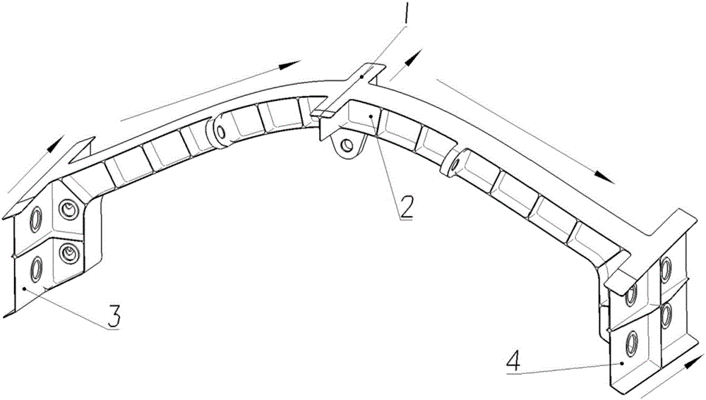
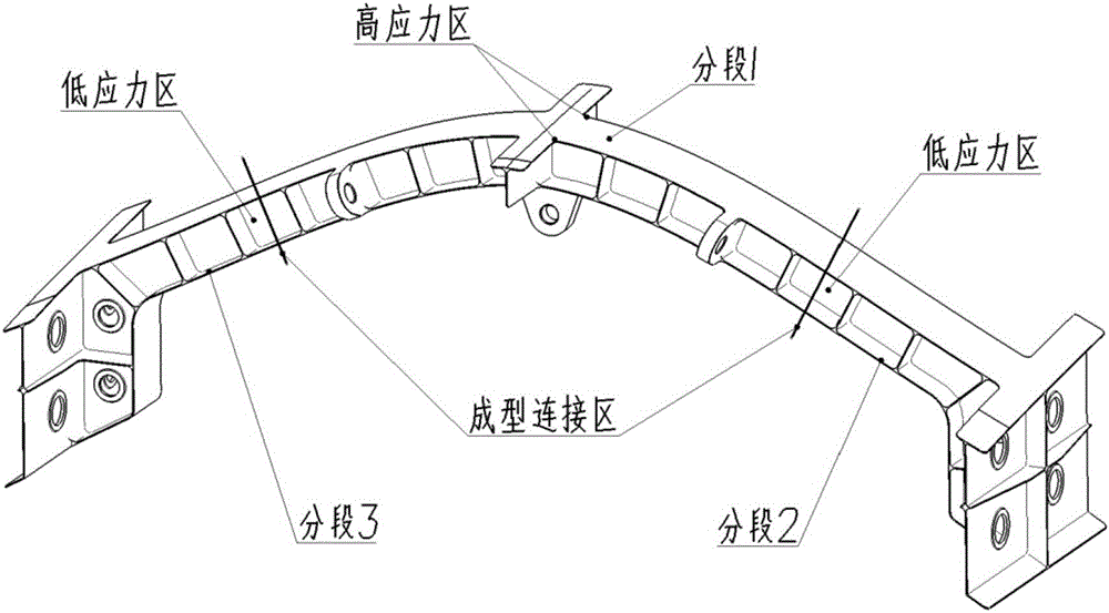
The invention relates to an optimum design method of an entire grid beam. By use of the electron beam fuse deposition molding technology, the method specifically comprises the following steps: step one, optimizing a structure size of a component according to a grid beam structure design allowable value given by design input to obtain an optimized size parameter; step two, determining force directions of different sections according to the size parameter, and designing that a fiber placement path of each section of the component is consistent with the force direction in combination with the mechanics optimum of a fiber placement direction; step three, lowering stress concentration of a stress region higher than the design allowable value according to the design allowable value; step four, if the entire grid beam is the component with high length ratio and stiffness mutation, first dividing the entire grid beam into a plurality of sections to be synchronously molded, and then performing the centralized molding connection. By use of the optimum design method of the entire grid beam disclosed by the invention, the process feasibility of the entire grid beam based on the electron beam fuse deposition molding technology can be guaranteed, and the strength, rigidity, the life and other design requirements can be satisfied at the same time.

Description

technical field [0001] The invention belongs to the field of aircraft structure design, and in particular relates to an optimal design method for a frame beam integral part. Background technique [0002] The main load-bearing skeleton of the traditional aircraft fuselage structure is composed of the transverse member of the reinforcement frame and the longitudinal member of the fuselage girder through mechanical connection. This combination structure has the following disadvantages: the connection parts, fasteners, and process sink more, and the weight cost is high; the connection area is prone to stress concentration, resulting in structural fatigue failure; various parts require multiple molds and tools to manufacture, and the assembly process is cumbersome. The production cycle is long and the cost is high. These factors are the bottlenecks restricting the development of aircraft fuselage structure design. [0003] Compared with the conventional combined frame, the fram...

Claims


Application Information

Patent Timeline
IPC IPC(8): G06F17/50
CPCG06F30/15G06F30/23
Inventor 王向明苏智星许平毕世权强博
Owner SHENYANG AIRCRAFT DESIGN INST AVIATION IND CORP OF CHINA
Learn More