OLED (Organic Light-Emitting Diode) driving circuit and OLED display panel

A driving circuit and driving current technology, which is applied to static indicators, instruments, etc., can solve problems such as changes in luminous brightness, easy drift, and affecting the quality of OLED display panels, and achieve the effect of stabilizing the driving current and improving image quality

Active Publication Date: 2017-04-26
WUHAN CHINA STAR OPTOELECTRONICS TECH CO LTD
View PDF7 Cites 20 Cited by
  • Summary
  • Abstract
  • Description
  • Claims
  • Application Information

AI Technical Summary

Problems solved by technology

Since the threshold voltage V of the drive thin film transistor T2 th prone to drift, causing the current flowing through the OLED I OLED changes, the current I flowing through the OLED OLED Changes will lead to changes in the luminance of the OLED, thereby affecting the image quality of the OLED display panel

Method used


Image

  • OLED (Organic Light-Emitting Diode) driving circuit and OLED display panel
  • OLED (Organic Light-Emitting Diode) driving circuit and OLED display panel
  • OLED (Organic Light-Emitting Diode) driving circuit and OLED display panel

Examples


Embodiment Construction

[0027] The following will clearly and completely describe the technical solutions in the embodiments of the present invention with reference to the accompanying drawings in the embodiments of the present invention. Obviously, the described embodiments are only some, not all, embodiments of the present invention. Based on the embodiments of the present invention, all other embodiments obtained by persons of ordinary skill in the art without making creative efforts belong to the protection scope of the present invention.

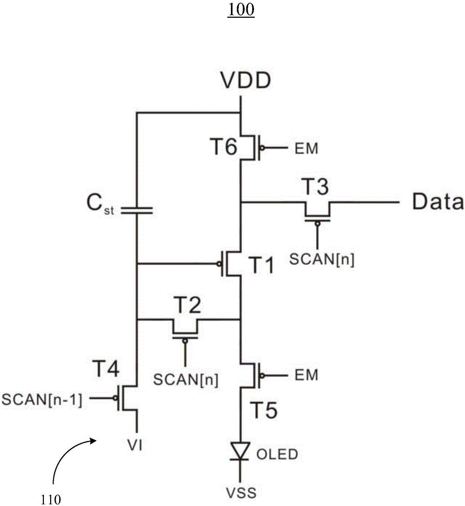
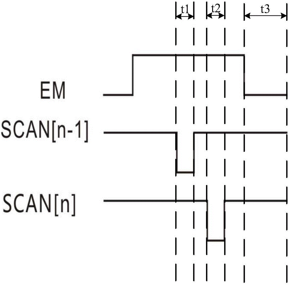
[0028] Please also refer to figure 2 and image 3 , figure 2 It is a schematic diagram of the OLED driving circuit in the first preferred embodiment of the present invention; image 3 for figure 2 The timing diagram of each signal of the OLED driving circuit is shown. The OLED driving circuit 100 is used for generating a driving current to drive an Organic Light-Emitting Diode (OLED). The OLED driving circuit includes a switching thin film transistor (...


PUM


Abstract

The invention provides an OLED (Organic Light-Emitting Diode) driving circuit and an OLED display panel. The OLED driving circuit comprises a switching thin film transistor, a driving thin film transistor, a storage capacitor and a compensating circuit, wherein each of the switching thin film transistor and the driving thin film transistor comprises a gate, a first end and a second end; the first end of the switching thin film transistor receives data signals; the gate of the switching thin film transistor receives nth scanning signals (SCAN[n]); the second end of the switching thin film transistor is electrically connected with the first end of the driving thin film transistor; the gate of the driving thin film transistor is connected with a voltage source through the storage capacitor; the second end of the driving thin film transistor is electrically connected with the positive electrode of the OLED through partial elements in the compensating circuit; the negative electrode of the OLED is loaded with low level; the compensating circuit is used for compensating changes of driving current flowing through the OLED due to drift of threshold voltage of the driving thin film transistor; the first end is a source, and the second end is a drain; or the first end is the drain and the second end is the source.

Description

technical field [0001] The invention relates to the display field, in particular to an OLED driving circuit and an OLED display panel. Background technique [0002] Organic Light-Emitting Diode (OLED) display panels are favored by people because of their thinness, lightness, energy saving, wide viewing angle, wide color gamut, and high contrast. The basic driving circuit of OLED such as figure 1 as shown, figure 1 It is a schematic diagram of an OLED driving circuit in the prior art. The driving circuit is used to drive the OLED, and the driving circuit includes a switching thin film transistor (Switch TFT) T1, a driving thin film transistor (Driver TFT) T2 and a storage capacitor Cst. This structure is also called 2T1C structure. The gate of the switching TFT T1 receives the scan information SCAN, the drain of the switching TFT T1 receives the data signal Data, and the source of the switching TFT T1 is electrically connected to the gate of the driving TFT T2. The source...

Claims


Application Information

Patent Timeline
IPC IPC(8): G09G3/3233
CPCG09G3/3233G09G2300/0861G09G2310/0251G09G2310/0262G09G2320/043G09G2320/0233G09G2300/0871G09G2300/043
Inventor 李骏
Owner WUHAN CHINA STAR OPTOELECTRONICS TECH CO LTD
Why Eureka
Try Eureka