Chambering and detaching tool for pin roll

A technology for dismantling tools and pins, applied in manufacturing tools, hand-held tools, etc., can solve the problems of difficult to control the degree of orifice expansion and easy cracking of the orifice, saving labor costs, improving production efficiency, and expanding the scope of application Effect

Inactive Publication Date: 2017-05-03
SHANGHAI AEROSPACE EQUIP MFG GENERAL FACTORY
View PDF5 Cites 4 Cited by
  • Summary
  • Abstract
  • Description
  • Claims
  • Application Information

AI Technical Summary

Problems solved by technology

The impact generated by knocking will affect the assembly accuracy of the product, and this method is difficult to control the degree of orifice expansion, and the orifice is easy to crack

Method used


Image

  • Chambering and detaching tool for pin roll
  • Chambering and detaching tool for pin roll
  • Chambering and detaching tool for pin roll

Examples


Embodiment Construction

[0015] The present invention will be described in further detail below in conjunction with the accompanying drawings and embodiments.

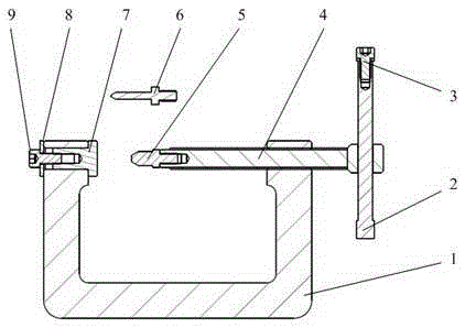
[0016] figure 1 It is a structural diagram of the pin assembly tool involved in the present invention, which includes a base 1, a swing rod 2, a screw A3, a screw rod 4, a reaming pin 5, an ejector pin 6, a spacer 7, a washer 8, and a screw B9.

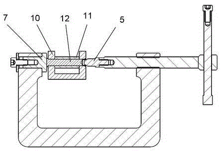
[0017] Such as figure 2 As shown, when the pin shaft is expanded, install the reaming pin 5 to the screw rod 4. The diameter of the reaming pin 5 matches the aperture of the product pin shaft, and the angle of the conical surface of the head is 60°. The screw rod and the base are matched with M12H7 threads. Install spacer 7 at the other end of the base, and fix it with washer 8 and screw B9.

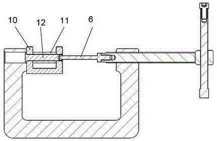
[0018] Such as image 3 As shown, when disassembling the pin shaft, install the ejector pin 6 to the screw 4. The diameter of the ejector pin 6 should be smaller than the diameter of the pin shaft, and the ...


PUM


Abstract

The invention relates to a chambering and detaching tool for a pin roll with a countersink at one end. When the pin roll is chambered, a chambering pin is mounted in a screw, a pin roll is clamped between a blanket and the chambering pin, and the countersink of the pin roll is chambered through the chambering pin through a spiral movement of the screw. When the pin roll is detached, the blanket, a washer, a screw and the chambering pin are detached, an ejector pin is mounted in the screw, and the ejector pin ejects the pin roll out of a mounting part through the spiral movement of the screw. Compared with other accomplishing means, the hole expanding and detaching processes are accomplished by one person; the hole expanding hole is steady, and the product is not impacted; the hole expanding extent is controllable, and the orifice is free of a cracking phenomenon; with adoption of a replaceable pressure head, the application range of the tool is expanded, and the tool is simple and feasible, and the labor cost is saved and the production efficiency is improved.

Description

technical field [0001] The invention relates to a pin shaft assembly tool, in particular to a pin shaft expansion and removal tool with a counterbore at one end. Background technique [0002] The large-scale extension mechanism of the space station is composed of many extension units. Each extension unit is composed of a triangular frame, hinge rod, telescopic rod, etc. In order to meet the product connection reliability and weight reduction requirements, each movable part is fixed by a pin connection. There is a blind hole at one end of the pin shaft. After the pin shaft is loaded into the two parts, the blind hole opening needs to be expanded. The original reaming method requires the cooperation of two people. One person holds the pad to pad one end of the pin shaft firmly, and the other uses a hammer and a taper pin to knock the expansion hole on the hole of the pin shaft; the disassembly process is similar, and the taper pin with a smaller diameter is replaced. Tap the ...

Claims


Application Information

Patent Timeline
IPC IPC(8): B25B27/00
CPCB25B27/00
Inventor 杨文涛杨晓慧祁峰金纯洁张富晶夏巧伟
Owner SHANGHAI AEROSPACE EQUIP MFG GENERAL FACTORY
Why Eureka
Try Eureka