Real-time monitoring device for bridge deflection based on laser signals

A laser signal and bridge deflection technology, applied in the direction of measuring devices, optical devices, instruments, etc., can solve the problems of inconvenient installation, distance limitation, manual reading, etc., and achieve long signal transmission distance, convenient installation and debugging, and simple structure compact effect

Inactive Publication Date: 2017-05-03
CHANGSHA UNIVERSITY OF SCIENCE AND TECHNOLOGY
View PDF6 Cites 6 Cited by
  • Summary
  • Abstract
  • Description
  • Claims
  • Application Information

AI Technical Summary

Problems solved by technology

The connected liquid level settlement deflection detection system is widely used, but this method is inconvenient to install on site, and the measurement accuracy is low
There are also linear displacement measuring instruments such as dial indicator, dial gauge, deflection gauge, etc. Although the accuracy is high, it needs to set up a bracket, which has relatively high requirements for the measurement environment.
Optical instruments such as levels, theodolites, and total stations have high precision, but there are also some shortcomings, such as being limited by distance, requiring manual readings, and not being able to measure continuously for a long time, etc.
There are also relatively new measuring devices using electronic devices such as LEDs and CCDs, but the measuring distance and accuracy are not as good as more advanced devices

Method used


Image

  • Real-time monitoring device for bridge deflection based on laser signals
  • Real-time monitoring device for bridge deflection based on laser signals
  • Real-time monitoring device for bridge deflection based on laser signals

Examples


Embodiment Construction

[0025] The present invention will be further described in detail below in conjunction with the accompanying drawings and specific embodiments.

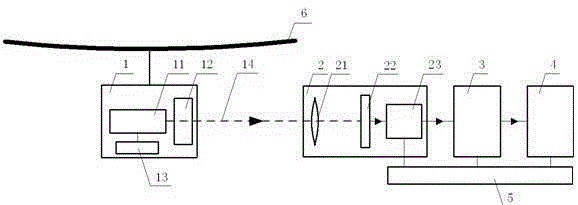
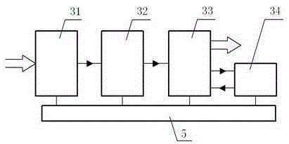
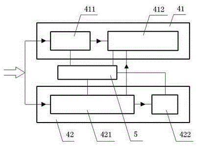
[0026] Such as figure 1 , figure 2 , image 3 with Figure 4 As shown, the bridge deflection real-time monitoring device based on the laser signal of the present embodiment comprises a laser signal transmitting unit 1, a signal receiving unit 2, an information processing unit 3 and a display and an alarm unit 4, and the laser signal transmitting unit 1 comprises a laser signal source 11, The beam expander lens system 12 and the signal source power supply 13, the beam expander lens system 12 is placed in the laser signal source 11 signal emission direction just ahead, the beam expander lens system 12 expands the laser beam that the laser signal source 11 sends to and suitable size, ensures When the vertical displacement of the bridge occurs, there is a light beam incident on the imaging lens system 21 of the receiving unit 2, the l...


PUM


Abstract

The invention discloses a real-time monitoring device for the bridge deflection based on laser signals, which comprises a laser signal transmitting unit (1), a signal receiving unit (2), an information processing unit (3) and a display and alarm unit (4), wherein the laser signal transmitting unit (1) comprises a laser signal source (11), a beam expanding lens system (12) and a signal source power supply (13), the laser signal transmitting unit (1) is placed below a midpoint of a monitored bridge (6) so as to reflect the bridge deflection, the signal receiving unit (2) comprises an imaging lens system (21), a displacement sensor PSD (22) and a micro current amplifying circuit (23), the information processing unit (3) is connected with an output end of the signal receiving unit (2), and the display and alarm unit (4) is connected with an output end of the information processing unit (3). The real-time monitoring device has the advantages of long monitoring distance, high precision, high anti-interference ability, simple structure, convenient installation, real-time data display, automatic early warning and the like.

Description

technical field [0001] The invention mainly relates to the field of bridge detection equipment, in particular to a laser signal-based real-time monitoring device for bridge deflection with high precision, simple structure, convenient installation, real-time data display and automatic early warning. Background technique [0002] The displacement of the bridge structure under the action of external load and environmental factors is an important parameter in the assessment of the safety state of the bridge structure. The monitoring of this parameter can avoid the occurrence of bridge accidents. A bridge deflection monitoring system is established to measure and display the bridge deflection in real time. When the bridge operation status is abnormal, an early warning signal can be issued to ensure the safe operation of the bridge. [0003] Various instruments and devices are used to measure bridge deflection. The connected liquid level type settlement deflection detection syste...

Claims


Application Information

Patent Timeline
Patent Type & Authority Applications(China)
IPC IPC(8): G01B11/16
Inventor 彭润伍李乐翟芳华张笔雨
Owner CHANGSHA UNIVERSITY OF SCIENCE AND TECHNOLOGY
Why Eureka
Try Eureka