Rotor and method for manufacturing the rotor

A rotor and rotor shaft technology, applied in the field of rotors, can solve the problems of high centrifugal force permeability, durability and use, and achieve the effects of simple salient pole design, simple structure and high salient pole ratio

Inactive Publication Date: 2020-01-07
ABB (SCHWEIZ) AG
View PDF7 Cites 0 Cited by
  • Summary
  • Abstract
  • Description
  • Claims
  • Application Information

AI Technical Summary

Problems solved by technology

There is a need for high-speed applications, but high centrifugal forces and permeability issues in different rotor orientations lead to challenges in terms of durability and use

Method used


Image

  • Rotor and method for manufacturing the rotor
  • Rotor and method for manufacturing the rotor
  • Rotor and method for manufacturing the rotor

Examples


Embodiment Construction

[0036] The following embodiments are examples only. Although this specification may refer to "one" embodiment in several places, this does not necessarily mean that each reference is to the same embodiment, nor does it mean that a feature is only applicable to a single embodiment. Single features of different implementations may also be combined to provide other implementations. Furthermore, the words "comprising" and "comprising" should be understood not to limit the described embodiments to consist of only those features that have been mentioned, and these embodiments may also contain features / structures that are not specifically mentioned. .

[0037] It should be noted that while the drawings show various embodiments, they are diagrams showing only some structural shapes. It will be apparent to those skilled in the art that the described devices may include structures and shapes other than those described in the drawings and text. It should be understood that some struct...


PUM


Abstract

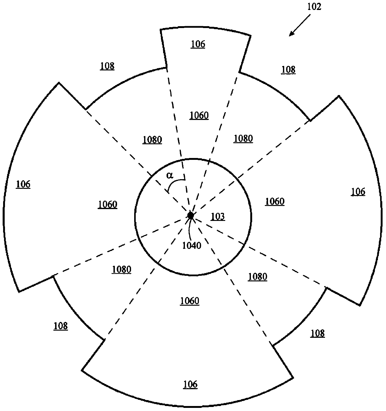
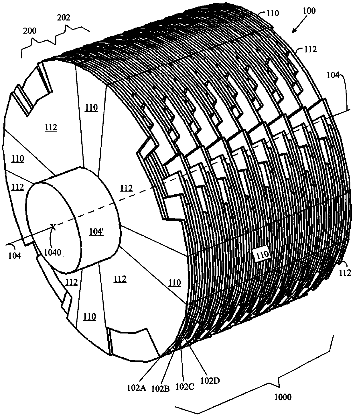
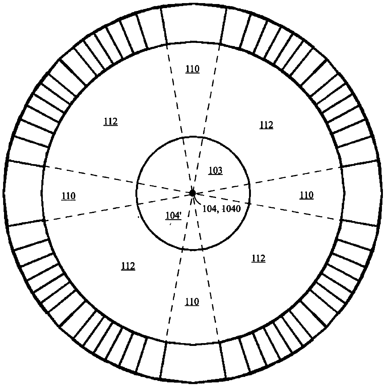
A rotor (100) of an electric motor (102) comprises a rotor shaft hole (103), first sectorial element sections (106) and second sectorial element sections (108), both of them being distributed alternatingly round a rotational axis (104) of the rotor (100). A distance of the outer contour of the second sectorial element sections (108) is shorter than that of the first sectorial element sections (106) from the rotational axis (104). A second sectorial element section (108) is overlapped with the first sectorial element section(s) (106) of other rotor element(s) (102) seen in a direction of the rotational axis (104). The rotor (100) comprises magnetic flux guides (150, 150', 152, 154, 154', 156, 158) which are configured to continue thorough the rotor (100) between the rotor shaft hole (103) and the circumference of the projection of the rotor (100) seen in the direction of the rotational axis (104).

Description

technical field [0001] The present invention relates to rotors, in particular rotors for electric motors, and methods of manufacture thereof. Background technique [0002] In one of the most common rotor configurations today, magnets are mounted on the surface of the rotor. This structure is simple and easy to manufacture. However, the surface magnets are not well protected and it is difficult to keep them still on the rotor surface especially at high rotational speeds. The magnets are better protected by inserting them into the rotor surface or by covering them with pole shoes. Continuing this development, it is possible to make magnet embedding. The magnets are thus better protected within the rotor than if they were mounted on the surface of the rotor. [0003] One of the easiest and most useful ways to create embedded magnet and synchronous reluctance motors is to use a single piece rotor blade where some magnetic bridges of the structural piece are left during the c...

Claims


Application Information

Patent Timeline
Patent Type & Authority Patents(China)
IPC IPC(8): H02K1/22H02K15/02
CPCH02K1/246H02K1/2766
Inventor 杰雷·科莱赫迈宁
Owner ABB (SCHWEIZ) AG
Why Eureka
Try Eureka