Eureka AIR delivers breakthrough ideas for toughest innovation challenges, trusted by R&D personnel around the world.

Drive motor heat-dissipation device for mining electric locomotive

A technology for cooling devices and driving motors, which is applied in the direction of electromechanical devices, electric components, cooling/ventilation devices, etc. It can solve the problems of adding explosion-proof measures and not being able to work for a long time, so as to extend the working time, prolong the working time and save electric energy. Effect

Inactive Publication Date: 2017-05-03
罗浩
View PDF0 Cites 1 Cited by
  • Summary
  • Abstract
  • Description
  • Claims
  • Application Information

AI Technical Summary

Problems solved by technology

One is that the blower is driven by electric energy, the gas concentration in the mine must be considered, and explosion-proof measures need to be added
Second, the blower also uses the motor to work, and it will also generate heat, so it cannot work for a long time

Method used


Image

  • Drive motor heat-dissipation device for mining electric locomotive
  • Drive motor heat-dissipation device for mining electric locomotive

Examples


Embodiment 1

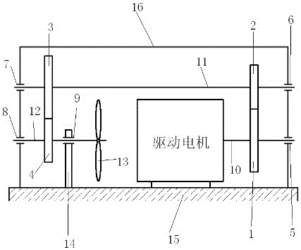
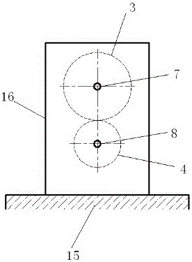
[0023] Such as figure 1 Shown: the driving motor cooling device of the mining electric locomotive, including the cooling device housing 16, gears, transmission shafts, rolling bearings, fan blades, and frame, the driving motor is installed in the cooling device housing 16, and the output spindle 10 of the driving motor is viewed from the left The driving motor, the first gear 1, and the first rolling bearing 5 are respectively installed to the right, and the third rolling bearing 7, the third gear 3, the second gear 2, and the second rolling bearing 6 are respectively connected to the first transmission shaft 11 from left to right. , The fourth rolling bearing 8, the fourth gear 4, the fifth rolling bearing 9, and the fan blade 13 are respectively installed on the second transmission shaft 12 from left to right. The first gear 1 meshes with the second gear 2 , and the third gear 3 meshes with the fourth gear 4 .

[0024] Both the drive motor and the heat sink housing 16 are f...


PUM


Abstract

The invention discloses a drive motor heat-dissipation device for a mining electric locomotive, and the device comprises a heat-dissipation device housing, gears, transmission shafts, rolling bearings, fan blades, and a rack. A drive motor is disposed in the heat-dissipation device housing, and a drive motor output shaft is provided with the drive motor, the first gear and the first rolling bearing from the left to the right. The first transmission shaft is connected with the third rolling bearing, the third gear, the second gear and the second rolling bearing from the left to the right. The second transmission shaft is provided with the fourth rolling bearing, the fourth gear, the fifth rolling bearing and the fan blades from the left to the right. The first gear is engaged with the second gear, and the third gear is engaged with the fourth gear. The device can be suitable for an occasion with the high gas density, cannot generate a large amount of heat after long-time operation, and can save the electric energy.

Description

technical field [0001] The invention relates to a cooling device for a driving motor of a mining electric locomotive. Background technique [0002] The working environment of mining electric locomotives is generally complex and chaotic, and the environment is underground with poor ventilation. In order to improve industrial efficiency and work progress, overloading often occurs, which will cause the temperature of the drive motor to rise. When it is overheated, it will seriously affect the service life of the electric locomotive. A common solution is to use a blower to dissipate heat from the drive motor, but there are some drawbacks in this way. One is that the blower is driven by electric energy, so the gas concentration in the mine must be taken into account, and explosion-proof measures need to be added. The 2nd, blower also utilizes electric motor to work, also can generate heat, can't carry out long-time work. Contents of the invention [0003] The object of the ...

Claims


Application Information

Patent Timeline
Patent Type & Authority Applications(China)
IPC IPC(8): H02K9/06H02K7/116
Inventor 罗浩
Owner 罗浩
Why Eureka
Eureka Blog
Learn More