Device and synchronization method for synchronous output between multichannel DDSs

An output device, multi-channel technology, applied in the microwave field to avoid changes

Inactive Publication Date: 2017-05-03
WUHAN BINHU ELECTRONICS
View PDF6 Cites 8 Cited by
  • Summary
  • Abstract
  • Description
  • Claims
  • Application Information

AI Technical Summary

Problems solved by technology

Due to the different cable transmission delays at different ambient temperatures, this type of synchronization method is limited by the fact that the operating ambient temperature of each cable must be the same

Method used


Image

  • Device and synchronization method for synchronous output between multichannel DDSs
  • Device and synchronization method for synchronous output between multichannel DDSs

Examples


Embodiment Construction

[0013] The present invention will be further described below in conjunction with the accompanying drawings and embodiments.

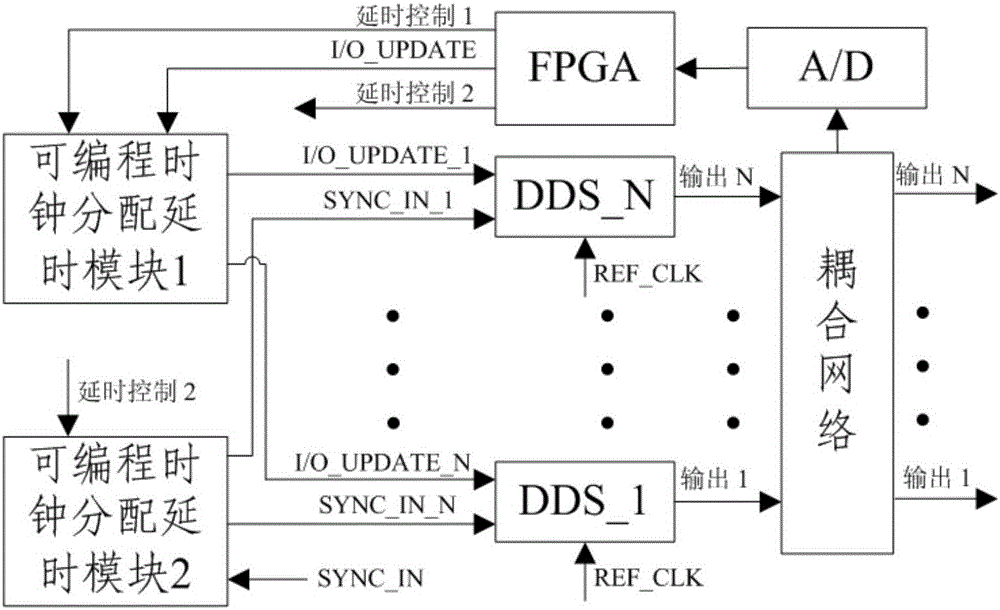
[0014] figure 2 It is a schematic block diagram of the realization circuit of the present invention. FPGA sends out I / O_UPDATE signal and controls one DDS to generate linear frequency modulation signal. The signal output by DDS is sent to FPGA after sampling by coupling network and A / D. FPGA uses digital deskewing method to detect and store The time difference between the DDS signal and the DDS signal is controlled separately to open and detect each DDS separately. By selecting the channel with the largest time difference among all DDS channels as the reference channel, the time difference is the standard channel time difference, and the time difference of each channel is subtracted from the standard channel time difference. It is the synchronous output time difference between channels. FPGA calculates the delay amount according to the synchronous out...


PUM


Abstract

The invention relates to the field of microwaves, the particularly relates to a device and a synchronization method for synchronous output between multichannel DDSs. According to the invention, a programmable clock distribution time delay module distributes signals I/O_UPDATE and SYNC_IN and is then connected to each DDS, output signals of each DDS are connected with an A/D conversion module through a coupling network, the A/D conversion module is connected with a control module, the control module is connected with the programmable clock distribution time delay module, the control module calculates the amount of time delay according to the synchronous output time difference and completes correction through controlling the programmable clock distribution time delay module to perform different time delays on the signals I/O_UPDATE and SYNC_IN of each multichannel DDS. The device and the synchronization method enable synchronous output between the multichannel DDSs to be not limited by a condition that the working environment temperature of the multichannel DDSs must be the same, and realize synchronous output between the multichannel DDSs at different working environment temperatures.

Description

technical field [0001] The invention relates to the microwave field, in particular to a multi-channel DDS synchronization output device and a synchronization method, which are applied to the radar field and communication products. Background technique [0002] The synchronous output between general multi-channel DDS (Direct Digital Frequency Synthesizer) mainly adopts the method of using the same length cables when the control and synchronous signals are distributed to each DDS. The circuit block diagram is as follows: figure 1 As shown, under the condition that REF_CLK (reference clock) arrives at each DDS synchronously, use cables of the same length to distribute signals such as I / O_UPDATE (input / output update pulse) and SYNC_IN (synchronous input) to ensure The data of each channel is updated and processed at the same time inside the DDS, so that the multi-channel DDS can output signals synchronously. Since cable transmission delays are different at different ambient tem...

Claims


Application Information

Patent Timeline
Patent Type & Authority Applications(China)
IPC IPC(8): H04J3/06
CPCH04J3/0685
Inventor 王伟李宏斌辛鹏刘斌刘磊
Owner WUHAN BINHU ELECTRONICS
Why Eureka
Try Eureka