Puncture guide device and puncture method

A technology for guiding devices and ultrasonic probes, which is applied in the direction of puncture needles, surgical navigation systems, trocars, etc., which can solve the problems of multiple spaces and the overall volume of the device, so as to shorten the puncture time, improve the puncture efficiency and success rate, and facilitate the operation. The effect of freehand puncture operation

Pending Publication Date: 2017-05-10
SONOSCAPE MEDICAL CORP
View PDF4 Cites 0 Cited by
  • Summary
  • Abstract
  • Description
  • Claims
  • Application Information

AI Technical Summary

Problems solved by technology

[0004] However, in the devices of the above two technologies, on the one hand, the overall volume of the device takes up too much space, and on the other hand, it is necessary to manually adjust the position of the laser light source to meet the needs of use.

Method used


Image

  • Puncture guide device and puncture method
  • Puncture guide device and puncture method
  • Puncture guide device and puncture method

Examples


Embodiment Construction

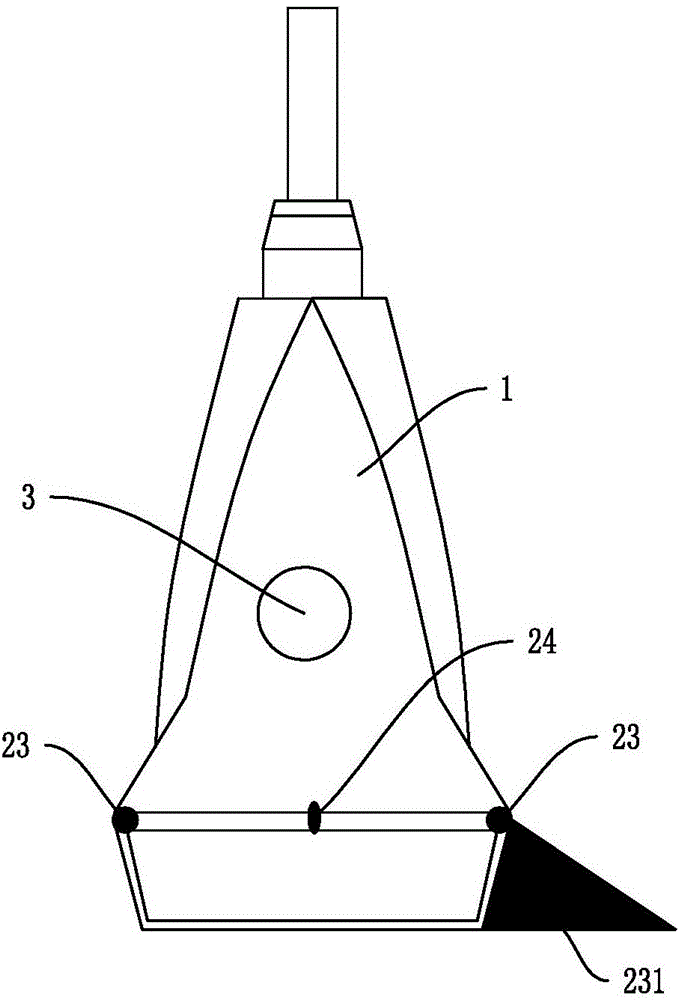
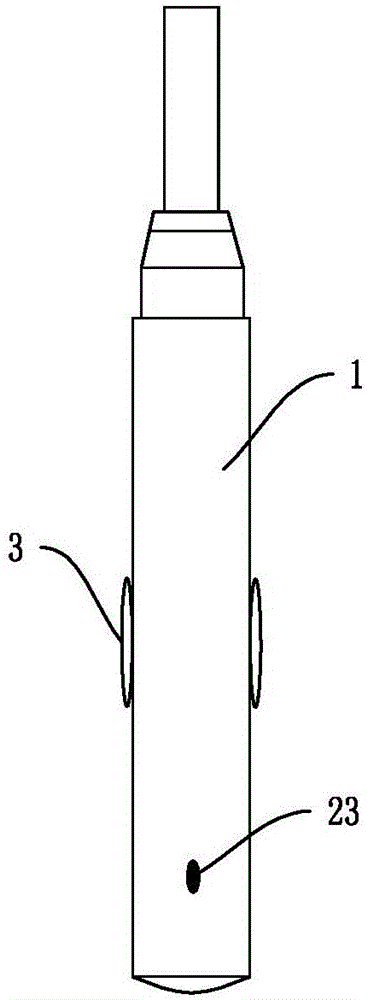
[0029] Such as figure 1 and figure 2 The puncture guiding device shown is mainly used for cooperating with the ultrasonic probe 1 for freehand puncture, and is directly installed on the casing of the ultrasonic probe 1 .

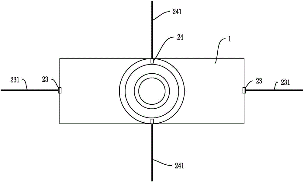
[0030] The ultrasonic probe 1 can be one of a linear array probe, a convex array probe, and a phased array probe. The main part of the guiding device is the navigation light source. Such as figure 1 As shown, the luminescence of the navigation light source can be projected to the side and downward of the ultrasonic probe 1, and project a "one"-shaped projection surface on the plane where the bottom end of the ultrasonic probe 1 is located, as shown in image 3 . When the ultrasonic probe 1 is in use, the plane where the bottom end of the probe is located can roughly be regarded as the surface where the body surface of the target to be punctured is located.

[0031] The above-mentioned navigation light source can be controlled by the installation positi...


PUM


Abstract

The invention discloses a puncture guide device and a puncture method, applied to an ultrasonic probe. The guide device is arranged on an ultrasonic probe shell; the guide device comprises a navigation light source; the navigation light source can project a linear projection plane on a to-be-punctured object; and the projection plane is located in a lateral direction of the ultrasonic probe. The puncture guide device provided by the invention, by virtue of the navigation light source and the generated projection plane thereof, can rapidly guide in-plane puncture, so as to facilitate a bared-hand puncture operation, improve puncture efficiency and a success rate and to shorten a puncture time. The puncture guide device provided by the invention is applicable to ultrasonic puncture.

Description

technical field [0001] The invention relates to the field of ultrasonic puncture, in particular to a puncture guiding device and a puncture method. Background technique [0002] When ultrasonic equipment is used for visual puncture, the current puncture methods are generally divided into manual puncture or puncture with a puncture frame. Manual puncture relies on the doctor's experience to find and make the puncture needle enter the ultrasound scanning plane. Its disadvantage is that it cannot quickly and accurately determine whether the needle insertion point is correct, especially when the puncture needle is far away from the probe. The ultrasound probe puncture frame provides guide grooves and corresponding puncture angle guide wires to ensure that the puncture needle enters the scanning plane. Needle angle, especially not suitable for parallel needles. [0003] CN 104856763A discloses an ultrasonic puncture method and device. The probe sound beam direction indicator is...

Claims


Application Information

Patent Timeline
Patent Type & Authority Applications(China)
IPC IPC(8): A61B17/34A61B34/20
CPCA61B17/3403A61B2017/3413
Inventor 向斌赵士娜梁峭嵘许龙
Owner SONOSCAPE MEDICAL CORP
Why Eureka
Try Eureka