A gas-liquid mixing device

A technology of gas-liquid mixing and mixing chamber, which is applied in fire rescue and other fields, can solve the problems of low foaming ratio and poor foaming ability, and achieve good foaming effect, uniform foam diameter and fast flow speed

Active Publication Date: 2022-07-26
成都启特安全技术有限责任公司
View PDF4 Cites 0 Cited by
  • Summary
  • Abstract
  • Description
  • Claims
  • Application Information

AI Technical Summary

Problems solved by technology

[0008] The purpose of the present invention is to provide a gas-liquid mixing device for the problems of insufficient contact between compressed air and mixed foam liquid in the prior art, and low foaming ratio and poor foaming ability caused by impact. The compressed air is contacted and mixed with the mixed foam liquid from multiple directions, so that the diameter of the formed foam is more uniform and the stability is better, which solves the problem of mixing and foaming the compressed air with the mixed foam liquid from one direction in the prior art. The gas-liquid mixing device has a simple structure. By fully contacting and impacting the compressed air with the mixed foam liquid, the mixed foam liquid is fully foamed, the foaming ratio is high, and the foaming effect is good.

Method used


Image

  • A gas-liquid mixing device
  • A gas-liquid mixing device
  • A gas-liquid mixing device

Examples


Embodiment 1

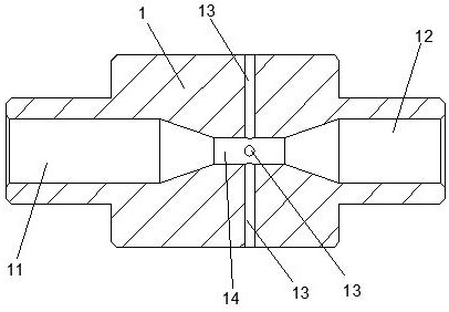
[0041] like figure 1 As shown, the gas-liquid mixing device includes a mixing main body 1, the mixing main body 1 includes a foam liquid inlet 11 and a foam liquid outlet 12 communicated with the foam liquid inlet 11, and the space between the foam liquid inlet 11 and the foam liquid outlet 12 is The foam liquid mixing chamber 14 is provided with a plurality of air inlets 13 for introducing compressed air, and the air inlets 13 communicate with the foam liquid inlet 11 .

[0042] The mixing body 1 includes a foam liquid inlet 11 and a foam liquid outlet 12. The foam liquid inlet 11 is used for introducing the mixed foam liquid, and the foam liquid outlet 12 is used for discharging (outputting) the foamed mixed foam liquid, and the foam liquid The inlet 11 is communicated with the foam liquid outlet 12, so that the foam liquid enters from one end of the inlet and then fully contacts, impacts, and foams in the foam liquid mixing chamber 14, and the foamed liquid is discharged fr...

Embodiment 2

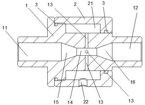
[0053] like figure 2 As shown, the gas-liquid mixing device includes a mixing main body 1, the mixing main body 1 includes a foam liquid inlet 11 and a foam liquid outlet 12 communicated with the foam liquid inlet 11, and the space between the foam liquid inlet 11 and the foam liquid outlet 12 is The foam liquid mixing chamber 14 is provided with a plurality of air inlets 13 for introducing compressed air, and the air inlets 13 communicate with the foam liquid inlet 11 .

[0054] The mixing body 1 includes a foam liquid inlet 11 and a foam liquid outlet 12. The foam liquid inlet 11 is used for introducing the mixed foam liquid, and the foam liquid outlet 12 is used for discharging (outputting) the foamed mixed foam liquid, and the foam liquid The inlet 11 is communicated with the foam liquid outlet 12, so that the foam liquid enters from one end of the inlet and then fully contacts, impacts, and foams in the foam liquid mixing chamber 14, and the foamed liquid is discharged f...

Embodiment 3

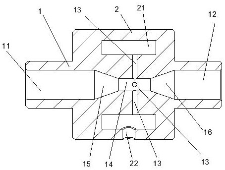
[0070] like image 3 As shown, the gas-liquid mixing device includes a mixing main body 1, the mixing main body 1 includes a foam liquid inlet 11 and a foam liquid outlet 12 communicated with the foam liquid inlet 11, and the space between the foam liquid inlet 11 and the foam liquid outlet 12 is The foam liquid mixing chamber 14 is provided with a plurality of air inlets 13 for introducing compressed air, and the air inlets 13 communicate with the foam liquid inlet 11 .

[0071] The mixing body 1 includes a foam liquid inlet 11 and a foam liquid outlet 12. The foam liquid inlet 11 is used for introducing the mixed foam liquid, and the foam liquid outlet 12 is used for discharging (outputting) the foamed mixed foam liquid, and the foam liquid The inlet 11 is communicated with the foam liquid outlet 12, so that the foam liquid enters from one end of the inlet and then fully contacts, impacts, and foams in the foam liquid mixing chamber 14, and the foamed liquid is discharged fr...


PUM


Abstract

The invention relates to the technical field of fire fighting equipment, in particular to a gas-liquid mixing device, comprising a mixing main body, the mixing main body comprises a foam liquid inlet and a foam liquid outlet communicating with the foam liquid inlet, and the foam liquid inlet and the foam liquid outlet are between the foam liquid inlet and the foam liquid outlet. There is a foam-liquid mixing chamber, and the foam-liquid mixing chamber is provided with a plurality of air inlets for introducing compressed air, and the air inlets are communicated with the foam liquid inlet. Contacting and mixing with the mixed foam liquid, the diameter of the formed foam is more uniform and the stability is better, and the problem that the compressed air is mixed and foamed with the mixed foam liquid from one direction in the prior art is solved, and the gas-liquid mixing device has a simple structure. , By fully contacting and impacting the compressed air and the mixed foam liquid, the mixed foam liquid is fully foamed, the foaming ratio is high, and the foaming effect is better.

Description

technical field [0001] The invention relates to the technical field of fire fighting equipment, in particular to a gas-liquid mixing device. Background technique [0002] In the fire fighting system, foam fire extinguishing is a more commonly used fire extinguishing method. The foam fire extinguishing method is adopted. Due to the low density of the foam, it can cover the surface of the flammable liquid. On the one hand, it can reduce the temperature of the liquid surface and cool the liquid surface. On the other hand, after the liquid is completely covered by foam, an insulating layer is formed to cut off the contact between the air and the liquid surface, so as to achieve the purpose of extinguishing the fire. The foam fire extinguishing method can be used to extinguish Class A fires, and is very suitable for extinguishing Class B fires, such as gasoline, diesel and other liquid fires. [0003] When using the foam fire extinguishing method to extinguish the fire, it is ne...

Claims


Application Information

Patent Timeline
Patent Type & Authority Patents(China)
IPC IPC(8): A62C5/02
CPCA62C5/002A62C5/02
Inventor 张璐王靖胡翔冉辉汤茂斌
Owner 成都启特安全技术有限责任公司
Why Eureka
Try Eureka