A heat shield welding tool

A technology of welding tooling and heat shield, which is applied in the field of mechanical processing, can solve the problems of scrapped parts and low product qualification rate, and achieve the effects of improving production efficiency, improving weld quality, and reducing labor intensity

Active Publication Date: 2018-09-21
CHINA HANGFA GUIZHOU LIYANG AVIATION POWER CO LTD
View PDF7 Cites 0 Cited by
  • Summary
  • Abstract
  • Description
  • Claims
  • Application Information

AI Technical Summary

Problems solved by technology

With this process, due to the short ends of the ribs, the cumulative error is greater than 1mm after two markings at the same time, resulting in the centerline of the drawn weld deviates from the center line of the ribs by more than 1mm, resulting in the deviation of the center of the weld from the center of the ribs to the ribs In addition, the inner heat insulation cylinder is welded through, resulting in scrapped parts and low product qualification rate

Method used


Image

  • A heat shield welding tool
  • A heat shield welding tool
  • A heat shield welding tool

Examples


Embodiment Construction

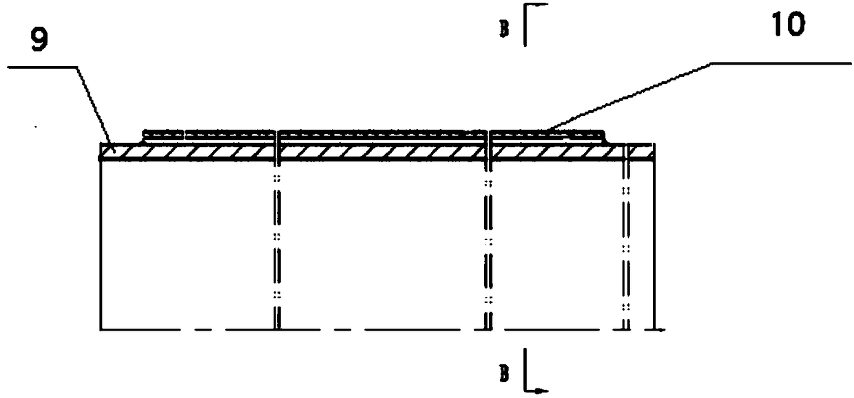
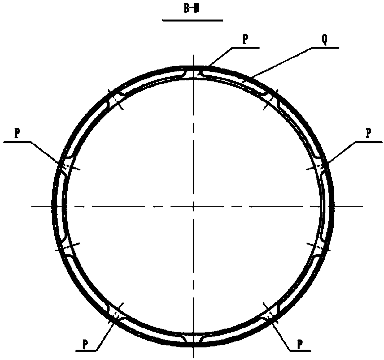
[0016] Such as figure 1 and 2 As shown, the heat shield assembly is connected by the inner heat insulation cylinder 9 and the outer heat insulation cylinder 10 by vacuum electron beam welding, and the uniform distribution between the inner heat insulation cylinder 9 and the outer heat insulation cylinder 10 is required Five ribs are welded, the joint form is lap joint, the weld is at the center of the rib, and the offset center is not more than 1mm. figure 2 P in represents the uniform distribution of 10 ribs, and Q is the cavity between the ribs; figure 2 There are 10 ribs drawn in the figure. When welding, only 5 ribs need to be welded evenly; in order to achieve the purpose of reducing scribing and improving efficiency, the following scheme is adopted:

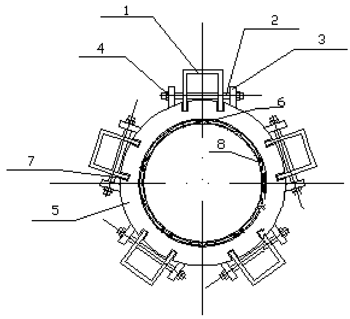
[0017] A fixture is now designed, a heat shield welding tool, including a circular fixture body 5, and lead frames 1 are evenly distributed on the outside of the fixture body 5 in the circumferential direction, and the ...


PUM


Abstract

The invention discloses a heat isolation screen welding tool. The heat isolation screen welding tool comprises an annular clamp body (5). Lead frames (1) are evenly distributed on the outer side of the clamp body (5) in the circumferential direction. The outer end faces of the lead frames (1) are parallel to the central axis of the clamp body (5). The central axis of the clamp body (5) is located in the vertical bisection plane of the outer end faces of the lead frames (1) in the width direction. Limiting blocks (6) are arranged on the circumference of the inner side of the clamp body (5). Every two limiting blocks (6) are arranged in one group and symmetrically arranged relative to the vertical bisection plane of the outer end faces of the lead frames (1) in the width direction. The distance between every two adjacent limiting blocks (6) is equal to the width of ribs. According to the heat isolation screen welding tool, three scribing procedures are omitted, the labor intensity of workers is lowered, and the component production efficiency is improved; and the welding line quality of components is improved, the welding qualification rate of the components is guaranteed, and the enterprise benefits are improved.

Description

technical field [0001] The invention belongs to the field of mechanical processing, and in particular relates to special tooling for heat shield welding. Background technique [0002] Such as figure 1 As shown, the heat shield assembly is assembled by the inner heat insulation cylinder and the outer heat insulation cylinder and connected by vacuum electron beam welding. Five ribs evenly distributed between the inner heat insulation cylinder and the outer heat insulation cylinder are required to be welded , the joint form is lap joint, the weld is at the center of the rib, and the offset center is not greater than 1mm. Since the outer heat insulation cylinder completely blocks the five ribs on the inner heat insulation cylinder, in order to ensure that the weld seam deviates from the center of the ribs by no more than 1mm, a line is drawn at the end of the ribs of the inner heat insulation cylinder, and then the line is led to the outer insulation On the heat cylinder, weld...

Claims


Application Information

Patent Timeline
Patent Type & Authority Patents(China)
IPC IPC(8): B23K15/00
CPCB23K15/0026B23K15/0046
Inventor 方志忠李立新涂强刘兴红
Owner CHINA HANGFA GUIZHOU LIYANG AVIATION POWER CO LTD
Why Eureka
Try Eureka