Drilling and milling device for adjustment sheet type part

A technology for adjusting pieces and parts, applied in positioning devices, metal processing machinery parts, clamping, etc., can solve problems such as difficult to ensure the processing size, hinder the opening of the adjusting pieces, long processing cycle, etc., to achieve convenient processing and use, and shorten the processing cycle , Reduce the effect of clamping error

Inactive Publication Date: 2017-05-10
CHINA HANGFA GUIZHOU LIYANG AVIATION POWER CO LTD
View PDF5 Cites 2 Cited by
  • Summary
  • Abstract
  • Description
  • Claims
  • Application Information

AI Technical Summary

Problems solved by technology

Since the adjusting piece often needs to be opened and closed when the nozzle is retracted and expanded, there is a higher requirement for the hole distance from the bottom plate 1 of the adjusting piece to the mounting pin shaft. If the hole distance is small, it will hinder the opening of the regulating piece. Adjustability of the spout
Therefore, in the processing of adjusting piece parts, it is necessary to carry out processes such as drilling and reaming, milling lugs, etc. However, as a clamping method for drilling and reaming and milling lugs for adjusting piece parts, it is generally performed on a set of milling fixtures first. Carry out milling lugs, and then drill and ream holes on the drilling and reaming jig, but as the processing of adjusting piece parts, it not only needs to ensure the size of the holes at the lugs from the bottom plate, but also the depth of the milling lugs (dimensions from the center of the hole), therefore, it is difficult to ensure the processing size with multiple clamping methods; especially the clamping deformation of thin-walled parts makes the processing of the distance from the bottom plate to the center of the hole unstable, which in turn affects the product performance, and the processing cycle is long and labor-intensive

Method used


Image

  • Drilling and milling device for adjustment sheet type part
  • Drilling and milling device for adjustment sheet type part
  • Drilling and milling device for adjustment sheet type part

Examples


Embodiment Construction

[0025] The technical solution of the present invention is further described below, but the scope of protection is not limited to the description.

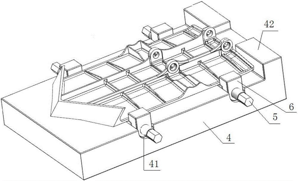
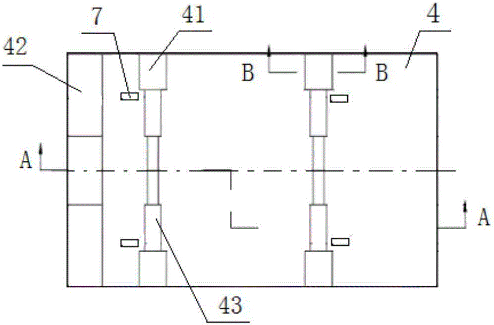
[0026] Such as figure 2 As shown, a drilling and milling device for regulating piece parts according to the present invention includes a fixture main body 4, a centering screw 5 and a centering pressure plate 6. The fixture main body 4 is provided with a screw mounting groove 43, and the fixture main body 4 is located on the The two ends of the screw installation groove 43 are provided with a briquetting installation groove 41, the centering screw 5 is installed in the screw installation groove 43, and the centering pressure plate 6 is respectively set on the two ends of the centering screw 5 and placed in the briquetting installation groove 41, the fixture main body 4 is also provided with a support block 7 outside the screw mounting groove 43. The fixture adopts end face positioning and four-point support, and realizes automati...


PUM


Abstract

The invention discloses a drilling and milling device for an adjustment sheet type part. The drilling and milling device comprises a clamp body, centering screws and centering press plates. The clamp body is provided with screw mounting grooves, and press block mounting grooves are formed in the clamp body and located at the two ends of each screw mounting groove. The centering screws are mounted in the screw mounting grooves, the two ends of each centering screw are sleeved with the corresponding centering press plates which are arranged in the press block mounting grooves, and supporting blocks are further arranged on the clamp body and located outside the screw mounting grooves. By the adoption of the clamp body, when the adjustment sheet type part is clamped, except four supporting points and four pressing points opposite to the supporting points of the part, other thin walls are all in a non-stressed state, and part deformation caused by clamping can be greatly reduced; drilling and lug milling are completed through one-time clamping, and clamping errors are greatly reduced; and the center distance size can be guaranteed during drilling and reaming, and the device can be used for the lug milling procedure, so that clamp manufacturing and managing cost is saved, workers can conveniently use the device for machining on site, and the part machining cycle is shortened.

Description

technical field [0001] The invention belongs to the technical field of machining of aero-engine adjusting piece parts, and in particular relates to a drilling and milling device for adjusting piece parts. Background technique [0002] In aero-engines, regulator parts are widely used in the expansion nozzle of the engine. Regulator parts are thin-walled parts with a special structure. Such as figure 1 As shown, the structure of the part is a thin-walled plane part. There are many ribs 2 on the bottom plate 1 to increase the strength. There are two main ribs 3 on the bottom plate 1. There are 4 holes on the main rib 3 for assembly. Two pins. Since the adjusting piece often needs to be opened and closed when the nozzle is retracted and expanded, there is a higher requirement for the hole distance from the bottom plate 1 of the adjusting piece to the mounting pin shaft. If the hole distance is small, it will hinder the opening of the regulating piece. Adjustability of the sp...

Claims


Application Information

Patent Timeline
Patent Type & Authority Applications(China)
IPC IPC(8): B23Q3/06
CPCB23Q3/062
Inventor 赵万岳沈少杰
Owner CHINA HANGFA GUIZHOU LIYANG AVIATION POWER CO LTD
Why Eureka
Try Eureka