Opening closing and grinding structure for self-locking nut of aerospace vehicle

A self-locking nut, aerospace technology, applied in the aerospace field, can solve problems such as aerospace accidents, weakening of anti-loosening torque, loosening of connectors, etc., to achieve the effect of reducing cost, good anti-vibration ability, and avoiding excessive grinding

Active Publication Date: 2017-05-10
CHENGDU ZHIRONG ZHICHUANG INTPROP MANAGEMENT CO LTD
View PDF7 Cites 3 Cited by
  • Summary
  • Abstract
  • Description
  • Claims
  • Application Information

AI Technical Summary

Problems solved by technology

[0003] And in the above two types of closing methods, there are still some burrs or protrusions at the corners of the end of the self-locking nut after the closing process is completed, which will cause some burrs or protrusions to intervene when the self-locking nut and the bolt are mated. In the matching area between the bolt and the self-locking nut, it will affect the resistance effect caused by the radial elastic deformation of the closing part of the self-locking nut, and at the same time reduce the radial extrusion force on the surface of the bolt, and finally lead to the thread pair having The anti-loosening torque of the self-locking nut is weakened, that is, the self-locking function of the self-locking nut is invalid; and in a complex and precise aerospace vehicle, the loosening of the connecting parts of its core components will lead to serious aerospace accidents

Method used


Image

  • Opening closing and grinding structure for self-locking nut of aerospace vehicle
  • Opening closing and grinding structure for self-locking nut of aerospace vehicle
  • Opening closing and grinding structure for self-locking nut of aerospace vehicle

Examples


Embodiment 1

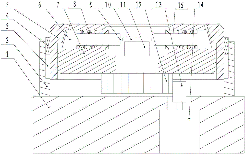
[0026] Such as figure 1 As shown, this embodiment includes a base 1 and a column 11 arranged on the base 1. A limit hole for matching with the self-locking nut 10 is opened on the upper end surface of the column 11, and an annular ring sleeved on the column 11 is also included. The closing plate 7 has a plurality of straight holes on its body along the radial direction of the closing plate 7, and the end of the top tightening block 6 moves through the straight holes and then extends to the middle of the closing plate 7, and at the end of the extension section of the top tightening block There is a grinding sheet 9 matching the closing part of the self-locking nut 10 on the upper part, and the grinding sheet 9 is facing the upper end of the limiting hole. In the prior art, the processing requirements for aerospace parts are relatively high. Except for the requirements of the material itself, the requirements for the processing technology of the parts are relatively strict. The...

Embodiment 2

[0029] Such as figure 1 As shown, the clamping block 6 is T-shaped, a block 15 is provided at the end of the straight hole close to the column 11, and the horizontal section of the clamping block 6 moves through the block 15, and the grinding sheet 9 is arranged on the The end of the horizontal section of the tight block 6 and the two ends of the vertical section 16 of the tight block 6 contact with the inner wall of the straight hole respectively. The top tight block 6 adopts a T shape, and the end of one side of the horizontal section of the top tight block 6 is connected to the midpoint of its vertical section 16, and the end of the horizontal section of the top tight block 6 moves through the block 15, and the top tight block 6 The two ends of the vertical section 16 are respectively in contact with the inner wall of the straight hole. At this time, compared with when the top tightening block body completely penetrates the straight hole, the contact area between the top ti...

Embodiment 3

[0032] Such as figure 1 As shown, it also includes a top ring 5 coaxial with the closing plate 7, the lower section of the inner wall of the top ring 5 is threadedly matched with the outer peripheral wall of the closing plate 7, and a protrusion is provided on the upper section of the inner wall of the top ring 5, And the protruding part is in contact with the end of the tightening block 6, and the top ring 5 is rotated to force the protruding part to push the tightening block 6 to move toward the middle of the closing disc 7 along the radial direction of the closing disc 7. When the jacking block 6 is driven, the inventor abandons the synchronous drive of multiple cylinders or oil cylinders, and adopts a relatively stable driving method, that is, the outer circumference of the closing disc 7 is provided with a top ring 5 threaded with it. The upper section of the inner side wall of the tight cover is provided with a protrusion, and the protrusion cooperates with the outer sid...


PUM


Abstract

The invention discloses an opening closing and grinding structure for a self-locking nut of an aerospace vehicle. The structure comprises a base and a stand column arranged on the base; a spacing hole which is matched with a self-locking nut is formed in the upper end surface of the stand column; the structure also comprises an annular opening closing plate arranged on the stand column in a sleeving manner; a plurality of straight holes are formed in the radial direction of the opening closing plate on a main body; after the end part of an ejecting block movably penetrates through the straight holes, the end of the ejecting block extends to the middle of the opening closing plate; and a grinding sheet which is matched with the opening closing part of the self-locking nut is arranged at the end part of the extended section of the ejecting block and the grinding sheet directly faces the upper end of the spacing hole. Aiming at the defects, the inventor develops a quick grinding and polishing device for the self-locking nut after completion of opening closing, removal of the burr or protrusion on the opening closing part of the self-locking nut is realized quickly, and besides, the follow-up treatment cost of numerous self-locking threads in the aerospace vehicle is reduced, so that the self-locking nut has good anti-vibration ability.

Description

technical field [0001] The invention relates to the field of aerospace, in particular to an aerospace self-locking nut grinding structure. Background technique [0002] For self-locking closing nuts used in aerospace and other industries, the closing is made after the nut is made according to the conventional process, and the closing part of the nut is extruded by extrusion method, so that the screw hole of the closing part is along the radial direction. Plastic deformation occurs, and the radial size of the screw hole at the closing part is smaller than the radial size of the screw connected to it, so that when the screw connected to the nut enters the deformed screw hole of the nut, it is caused by the elastic deformation of the screw hole The radial pressure makes the nut tightly connected with the screw to achieve the purpose of anti-loosening. According to the structure, size and service conditions of self-locking nuts, the closures are divided into two-point closures,...

Claims


Application Information

Patent Timeline
Patent Type & Authority Applications(China)
IPC IPC(8): B24B9/04
CPCB24B9/04
Inventor 缪可言
Owner CHENGDU ZHIRONG ZHICHUANG INTPROP MANAGEMENT CO LTD
Why Eureka
Try Eureka