Disc device and semiconductor integrated circuit and pick-up control method and vibration component test method

A technology of optical disc device and pickup head, applied in recording/reproducing by optical method, arrangement/installation of head, recording of information on magnetic disc, etc., can solve the difficulty of vibration resistance, short focal distance, loss of servo control and other problems to achieve the effect of improving vibration detection performance and improving vibration resistance

Inactive Publication Date: 2003-04-02
コラボイノベーションズインコーポレイテッド
View PDF0 Cites 12 Cited by
  • Summary
  • Abstract
  • Description
  • Claims
  • Application Information

AI Technical Summary

Problems solved by technology

[0012] However, when the optical disc device is used in a portable manner, it may be subject to strong vibration or shock in the focusing direction.
In this case, in the existing optical disc device, there is a problem that the focus servo will be confused, and even the servo control will be lost in severe cases.
[0013] In addition, with the continuous increase in the density of information stored on optical discs in the future, the focal length of the light beam used to read such high-density information is estimated to be shorter and shorter
When the focal length of the light beam is shortened, even small vibrations in the focus direction, which have been negligible until now, have a large influence on the signal reproduction
In this case, it is difficult to ensure sufficient vibration resistance for conventional optical disc devices that detect vibration only from tracking error signals.

Method used


Image

  • Disc device and semiconductor integrated circuit and pick-up control method and vibration component test method
  • Disc device and semiconductor integrated circuit and pick-up control method and vibration component test method
  • Disc device and semiconductor integrated circuit and pick-up control method and vibration component test method

Examples


Embodiment 1

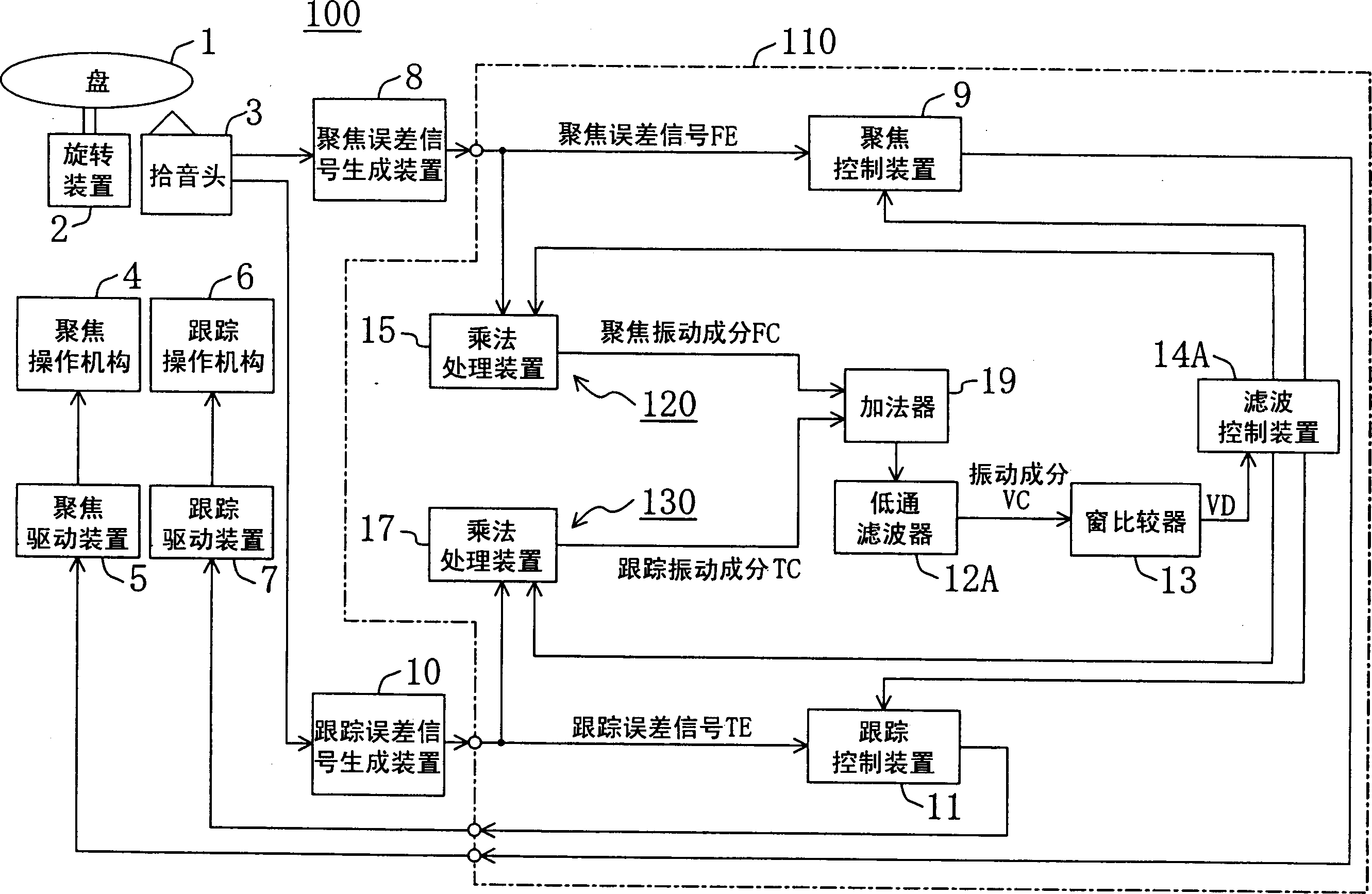
[0037] figure 1 The configuration of the optical disc device 100 according to Embodiment 1 of the present invention is shown. Next, the optical disc device 100 will be described in detail, but Figure 4 The components in the illustrated optical disc devices are the same, and the description thereof will be omitted by using the same reference numerals.

[0038] The optical disc device 100 includes: a focus component generator 120 that generates a focus vibration component FC from the focus error signal FE; a tracking component generator 130 that generates a tracking vibration component TC from the tracking error signal TE; Adder 19 for adding component TC; and low-pass filter 12A for extracting vibration component VC from the addition result of adder 19 (corresponding to the extracting means of the present invention). It performs focus control and tracking control of the pickup 3 according to the vibration component.

[0039] In addition, the focus component generation part ...

Embodiment 2

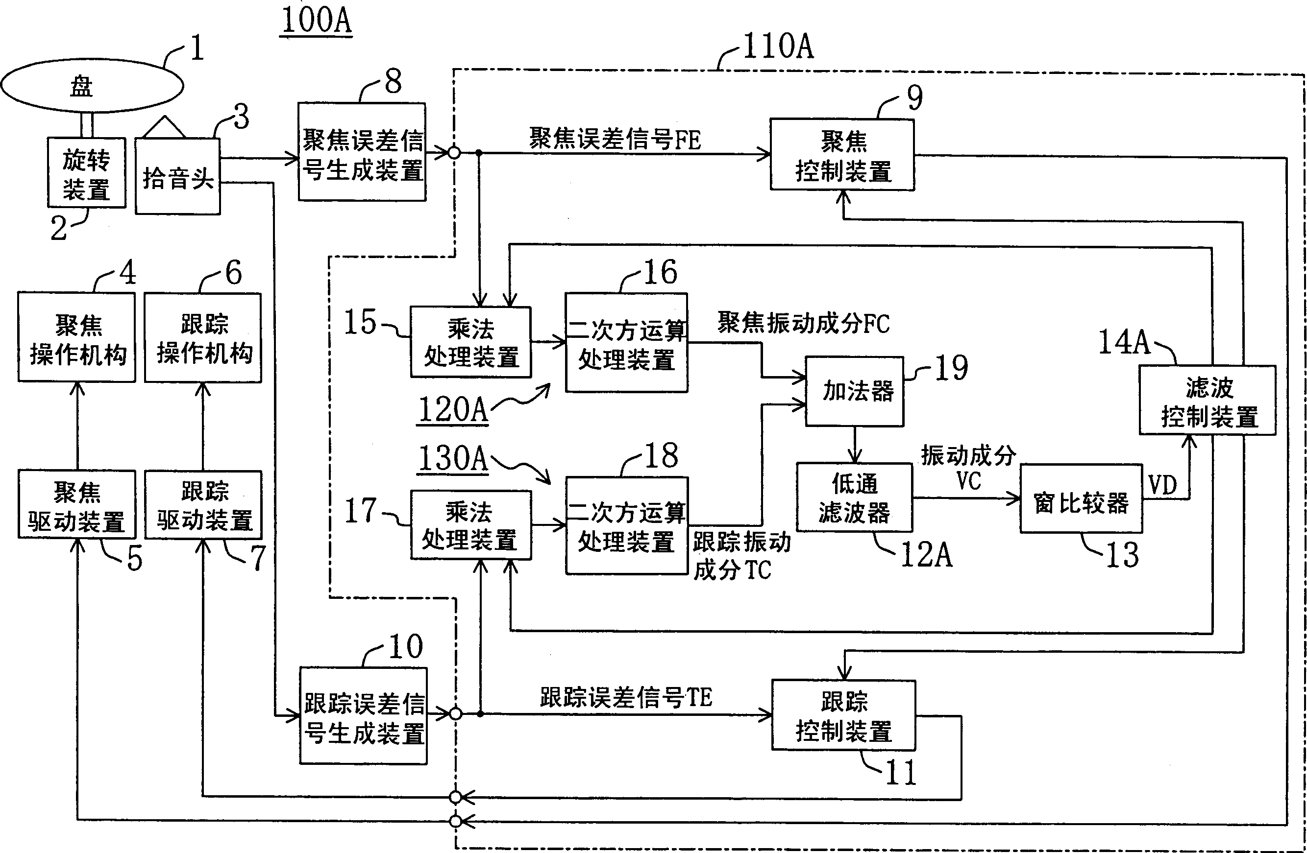
[0055] In the first embodiment described above, the multiplied focus error signal FE and tracking error signal TE are added as they are. However, when compound vibration occurs in the focus direction and the track direction, the phases of the focus error signal FE and the tracking error signal TE may be reversed, and the levels may be reversed. At this time, if the focus error signal FE and the tracking error signal TE are simply added together, the vibration components will be canceled out, so that accurate vibration detection may not be possible.

[0056] In the optical disc device according to the second embodiment of the present invention, even when the above-mentioned composite vibration occurs, accurate vibration components can be extracted and accurate vibration detection can be performed. figure 2 The configuration of an optical disc device 100A according to Embodiment 2 of the present invention is shown. Next, the optical disc device 100A according to Embodiment 2 o...

Embodiment 3

[0064] The optical disk device according to the third embodiment of the present invention is different from the second embodiment and responds to the case where compound vibration occurs.

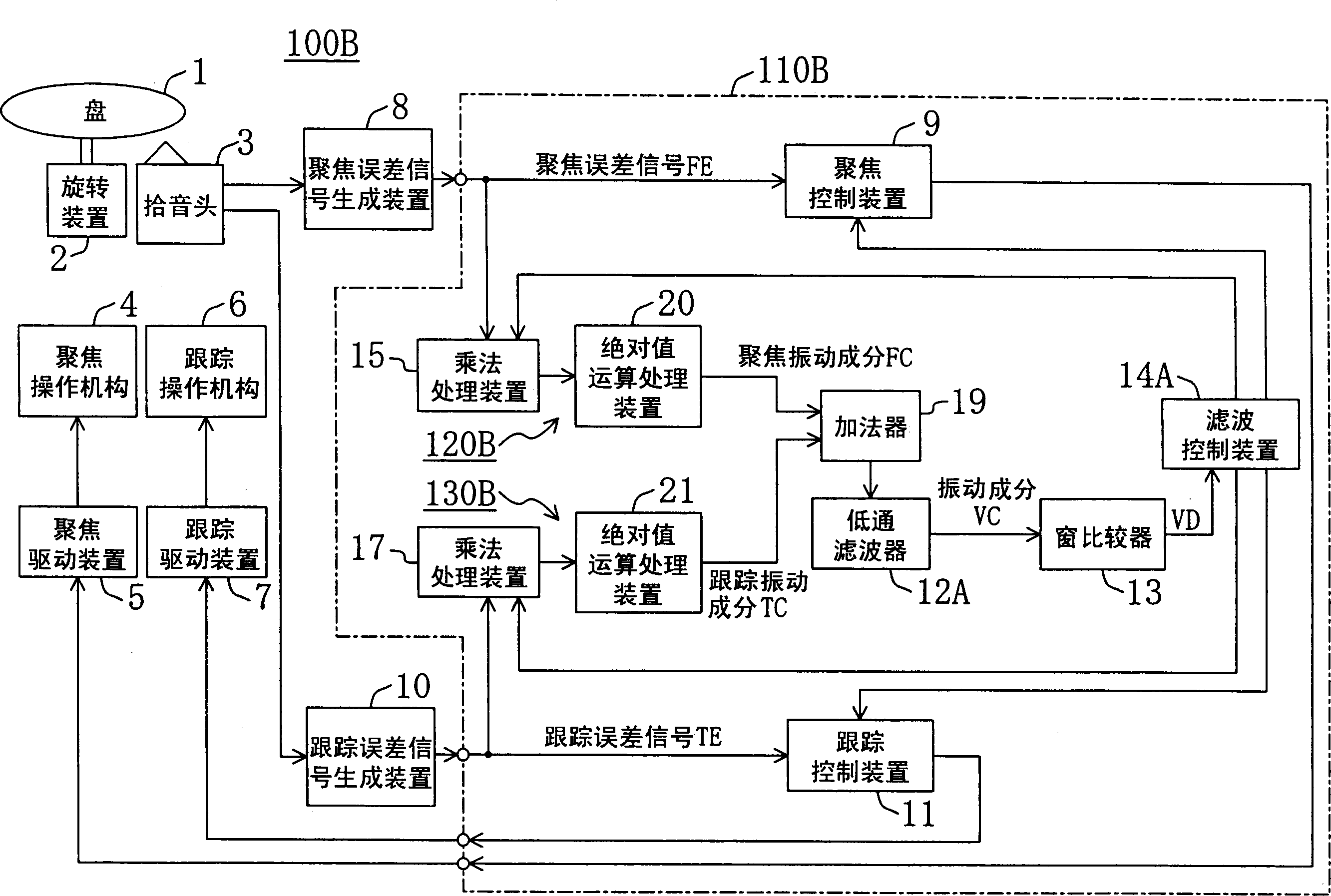
[0065] image 3 The configuration of an optical disc device 100B according to Embodiment 3 of the present invention is shown. Next, the optical disc device 100B will be described in detail, but the figure 1 and Figure 4 The same components in the shown optical disc devices are denoted by the same symbols and their descriptions are omitted.

[0066] The focus component generation unit 120B in the optical disc device 100B is composed of the multiplication processing unit 15 and the absolute value calculation processing unit 20 . Similarly, the tracking component generation unit 130B is composed of the multiplication processing unit 17 and the absolute value calculation processing unit 21 . In addition, both the focus component generation unit 120B and the tracking component generation un...


PUM


Abstract

A disc device and semiconductor integrated circuit and pick-up control method and vibration component test method are provided. An optical disk device is provided with a multiplication means for generating a focus vibration component FC from the focus error signal FE, a multiplication means for generating a tracking vibration component TC from the tracking error signal TE, an adder for adding the focus vibration components FC and TC, and a low-pass filter for extracting the vibration component VC from the added results. Thus, the vibration component VC is extracted considering not only vibrations in the tracking direction but also vibrations in the focus direction, so that vibrations acting on the device can be more accurately detected, and vibration resistance is increased. Tereby, it can increase the vibration resistance of an optical disk device with respect to vibrations in the focus direction.

Description

technical field [0001] The invention relates to an anti-vibration technology of an optical disk device, in particular to a technology for preventing the focus and tracking deviation of a pick-up head caused by external vibrations. Background technique [0002] In an optical disc device, in order to reproduce signals with high quality, it is desirable that the laser light spot is always kept in the best focus and best tracking state with respect to the signal storage surface. However, due to the mechanical precision of the disk rotation mechanism, the plane precision of the disk itself, and external interference factors, etc., there will be a certain degree of variation in the focus direction orthogonal to the signal storage surface and the track direction orthogonal to the track travel direction. vibration. Therefore, generally, an optical disk device has a focus operation mechanism driven in a focus direction and a tracking operation mechanism driven in a track direction w...

Claims


Application Information

Patent Timeline
Patent Type & Authority Applications(China)
IPC IPC(8): G11B7/09
CPCG11B7/0908G11B7/0946
Inventor 中田康夫春井正德
Owner コラボイノベーションズインコーポレイテッド
Why Eureka
Try Eureka