

Integral transfer straddle-type monorail PC track beam template
A straddle-type monorail and track beam technology, applied in the direction of molds, mold auxiliary parts, etc., to facilitate manufacturing and improve manufacturing efficiency
- Summary
- Abstract
- Description
- Claims
- Application Information
AI Technical Summary
Problems solved by technology
Method used
Image

Examples
Embodiment Construction
[0022] The present invention will be described in further detail below through specific embodiments in conjunction with the accompanying drawings.
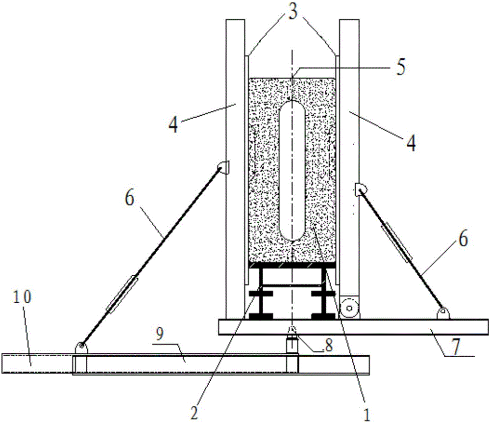
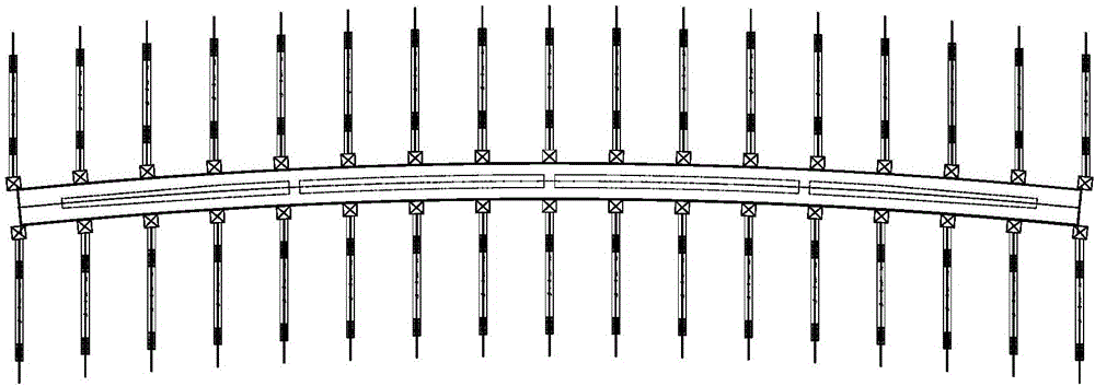
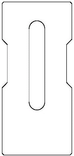
[0023] Considering that the existing formwork system has single applicability and is only suitable for PC beams of equal height, an integrally transferable straddle-type monorail PC track beam formwork is proposed. The formwork system can be used to prefabricate and produce large, medium and small-sized straight curved PC track beams of equal height and variable height within 30m. At the same time, when the control elevation of the top surface of the longitudinal center line of the bottom of the beam is determined, the template can be rotated as a whole to form the required track alignment, which improves the operability and efficiency of the beam body during beam manufacturing. If the cross-section of the beam remains unchanged (such as image 3 , Figure 5 (shown) only forms the linear shape required by the curve by the way of...
PUM
 Abstract
Description
Claims
Application Information