Unilateral cavity free foaming method

A cavity, unilateral technology, applied in the field of unilateral cavity free-form foaming, can solve the problems of substandard mechanical properties of products, affecting the cushioning performance of products, uneven cell structure, etc., and achieves good reference significance and good practice. Utility, the effect of reducing the cost of use and the cost of manufacturing the product

Active Publication Date: 2017-05-10
SHANDONG UNIV
View PDF2 Cites 7 Cited by
  • Summary
  • Abstract
  • Description
  • Claims
  • Application Information

AI Technical Summary

Problems solved by technology

In the traditional hot pressing molding process, the slurry is placed in the entire cavity and is in contact with the upper and lower mold surfaces. The foaming method of the prepared product is insufficient and the cell structure is uneven, which seriously affects the cushioning performance of the product and makes the mechanical properties of the product Not up to standard, and unable to carry out large-scale industrial production to meet market demand

Method used


Image

  • Unilateral cavity free foaming method
  • Unilateral cavity free foaming method
  • Unilateral cavity free foaming method

Examples


Embodiment 1

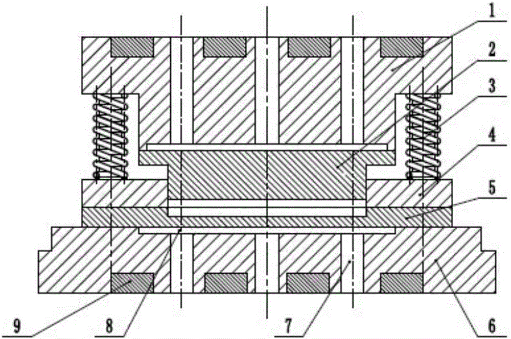
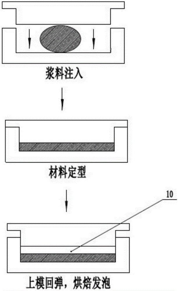
[0044] Such as figure 1 , as shown in Figure 2(a), the unilateral cavity free foaming method adopts a unilateral cavity free foaming mold including an aluminum alloy upper base 1, a breathable steel upper mold 2, a spring 3, an aluminum alloy retainer Plate 4, breathable steel lower mold 5, aluminum alloy lower base 6, vent hole 7, base sinking groove 8, electric heating plate 9 and unilateral foaming cavity 10, breathable steel upper mold 2 and breathable steel lower The mold 5 is combined to form the mold cavity, and the spring 3 is arranged between the aluminum alloy upper base 1 and the aluminum alloy baffle plate 4, such as image 3 As shown, the spring 3 is fixed on the lower surface of the aluminum alloy upper base 1, and after the upper and lower molds of the gas permeable steel are mold-closed to shape the biomass material product, the upper mold of the gas permeable steel rises a certain distance under the action of the resilience of the spring 3, so that the product...

Embodiment 2

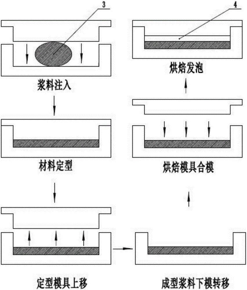
[0054] Unilateral cavity free foaming method, as shown in Figure 2(b),

[0055] 1) Set the biomass material in the lower mold;

[0056] 2) The first upper mold squeezes the biomass material in the lower mold to shape the biomass material. After a set time, the first upper mold is separated from the lower mold, and the biomass material in the lower mold is heated to the set first temperature ;The second temperature is 90-100°C, and the heating time is 1min;

[0057] 3) The lower mold is closed with the second upper mold. The length of the second upper mold that can be embedded in the lower mold is less than the length that the first upper mold can be embedded in the lower mold. Continue to heat the biomass material to the set second temperature , A unilateral foaming cavity is formed between the second upper mold and the lower mold; the biomass material is heated in the unilateral foaming cavity for a set time to realize baking and foaming of the unilateral cavity.


PUM

PropertyMeasurementUnit
thicknessaaaaaaaaaa

Abstract

The invention discloses an unilateral cavity free foaming method. A biomass material is arranged in a lower mold; an upper mold extrudes the biomass material in the lower mold for shaping by set time; the upper mold is deviated from the lower mold; the biomass material is foamed in the lower mold to realize unilateral cavity baking foaming; one of the upper mold and the lower mold is connected with a moving mechanism; and the upper mold is deviated from the lower mold under the effect of the moving mechanism after the set time of the upper mold and the lower mold extruding the biomass material. The unilateral cavity free foaming method largely shortens the product drying time, reduces the product original pulp use level, improves the product cell quality and the buffering performance, reduces the raw material use cost and the product production cost, is excellent in actual utility, and is excellent in reference on traditional mold production.

Description

technical field [0001] The invention relates to biomass materials, in particular to a method for free-style foaming of unilateral cavities. Background technique [0002] While plastic products provide convenience for human life, the products are non-degradable and cause serious harm to the environment; foamed biomass materials prepared from plant fibers and starch have become EPE due to their renewable raw materials and degradable products. A substitute for cushioning plastic products such as EPS. Existing foamed biomass materials are produced based on traditional thermocompression molding process. In the traditional hot pressing molding process, the slurry is placed in the entire cavity and is in contact with the upper and lower mold surfaces. The foaming method of the prepared product is insufficient and the cell structure is uneven, which seriously affects the cushioning performance of the product and makes the mechanical properties of the product It is not up to standa...

Claims


Application Information

Patent Timeline
Patent Type & Authority Applications(China)
IPC IPC(8): B29C44/02B29C44/58
CPCB29C44/027B29C44/585B29C44/588
Inventor 李方义张传伟谢麒徐婕金宗学陈帅王黎明李燕乐李剑峰郭安福
Owner SHANDONG UNIV
Why Eureka
Try Eureka