
Movable supporting platform special for installation of charging pile and working method of movable supporting platform

A mobile support and charging pile technology, applied in charging stations, electric vehicles, electric vehicle charging technology, etc., can solve the problems of charging piles without walking function, low work efficiency, high labor intensity, etc., to increase the effect of fixed installation, Easy to operate, good fixed support performance

Active Publication Date: 2017-05-10
潍坊冠来电气有限公司
View PDF5 Cites 22 Cited by
  • Summary
  • Abstract
  • Description
  • Claims
  • Application Information

AI Technical Summary

Problems solved by technology

[0004] In order to solve the above problems, the present invention provides a special mobile support platform for the installation of charging piles and its working method, which can solve the problem that the charging piles do not have the function of walking and the need Manual anti-lifting charging piles require manual fixed installation of charging piles, complicated operation, high labor intensity and low work efficiency. It can realize the stable shock-absorbing walking and self-stabilizing and fast fixing and installation functions of charging piles. It is easy to operate and low in labor intensity. , and has the advantages of being able to push and walk stably, without manual lifting, can be automatically installed and fixed, and has high work efficiency.

Method used


Image

  • Movable supporting platform special for installation of charging pile and working method of movable supporting platform
  • Movable supporting platform special for installation of charging pile and working method of movable supporting platform

Examples


Embodiment Construction

[0024] In order to make the technical means, creative features, goals and effects achieved by the present invention easy to understand, the present invention will be further described below in conjunction with specific illustrations.

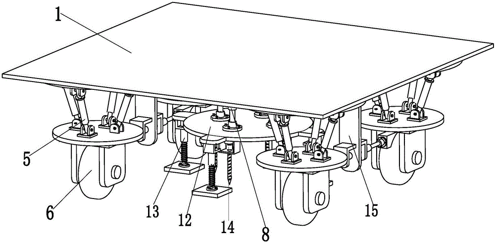
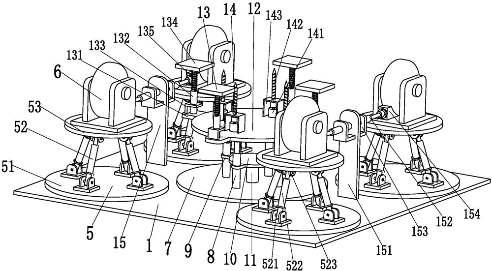
[0025] like figure 1 and figure 2 As shown, a special mobile support platform for charging pile installation includes a bottom plate 1, the upper end surface of the bottom plate 1 is used to install the existing charging pile, and four shock-absorbing support mechanisms 5 are symmetrically installed on the lower end surface of the bottom plate 1, each An omnidirectional wheel 6 is installed at the lower end of the shock-absorbing support mechanism 5, and the shock-absorbing support mechanism 5 provides a uniform shock-absorbing support force for the omnidirectional wheel 6. The four omnidirectional wheels 6 pass through four evenly distributed shock-absorbing support mechanisms 5 It can walk on the road under the push of external force, and wh...


PUM


Abstract

The invention relates to a movable supporting platform special for installation of a charging pile and a working method of the movable supporting platform. The movable supporting platform comprises a bottom plate. The upper end face of the bottom plate is used for installing the existing charging pile. Four damping and supporting mechanisms are symmetrically installed on the lower end face of the bottom plate. An omnidirectional wheel is installed at the lower end of each damping and supporting mechanism. An installation base table is installed in the middle of the lower end face of the bottom plate. The lower end face of the installation base table is evenly provided with four second hydraulic cylinders along the central axis. The middle of each second hydraulic cylinder is installed on a chucking lug, and the four chucking lugs of the four second hydraulic cylinders are evenly arranged on the outer wall of a positioning disc. The middle of the upper end face of the positioning disc is welded to a jacking column. The jacking column is welded to the middle of the lower end face of the installation base table. A lifting supporting table is welded to the top ends of the four second hydraulic cylinders. Four buffering and supporting mechanisms are evenly arranged on the outer wall of the lifting supporting table along the central axis. According to the movable supporting platform, the stable damping traveling function and the self-stabilizing fast fixing and installing function of the charging pile can be achieved.

Description

technical field [0001] The invention relates to the technical field of charging piles, in particular to a special mobile support platform for charging piles and a working method thereof. Background technique [0002] The charging pile can charge various types of electric vehicles according to different voltage levels. The charging pile can realize charging by timing, electricity meter, and amount, and can be used as a power purchase terminal for citizens. At present, it is mainly fixed on the ground or walls, and installed in public buildings, shopping malls, public parking lots, office buildings, government buildings and other public buildings or parking lots in residential quarters. The input end of the charging pile is directly connected to the AC grid, and the output end is equipped with a charging plug for charging the electric vehicle. [0003] There are already a variety of electric vehicles on the existing market, and electric vehicles have to be charged every time ...

Claims


Application Information

Patent Timeline
Patent Type & Authority Applications(China)
IPC IPC(8): B60L11/18B62B5/00
CPCB60L53/31B62B5/0083Y02T10/70Y02T10/7072Y02T90/12
Inventor 冒鹏飞
Owner 潍坊冠来电气有限公司
Learn More