
Multipoint water-in sludge in-situ reduction synchronous coupling nitrogen and phosphorus removal method

A synchronous coupling, denitrification and dephosphorization technology, applied in the direction of water/sludge/sewage treatment, water pollutants, biological sludge treatment, etc., can solve the problem that sludge cannot be reduced in situ, so as to reduce infrastructure investment and improve Effect of Nitrogen and Phosphorus Removal Efficiency

Inactive Publication Date: 2017-05-10
HEBEI UNIV OF ENG
View PDF3 Cites 2 Cited by
  • Summary
  • Abstract
  • Description
  • Claims
  • Application Information

AI Technical Summary

Problems solved by technology

[0005] However, what needs to be pointed out in this case is that the above-mentioned structure has the problem of being unable to reduce sludge in situ. Therefore, in this case, an anaerobic sludge storage tank was added in order to make reasonable improvements to the existing technology.

Method used


Image

  • Multipoint water-in sludge in-situ reduction synchronous coupling nitrogen and phosphorus removal method

Examples


Embodiment 1

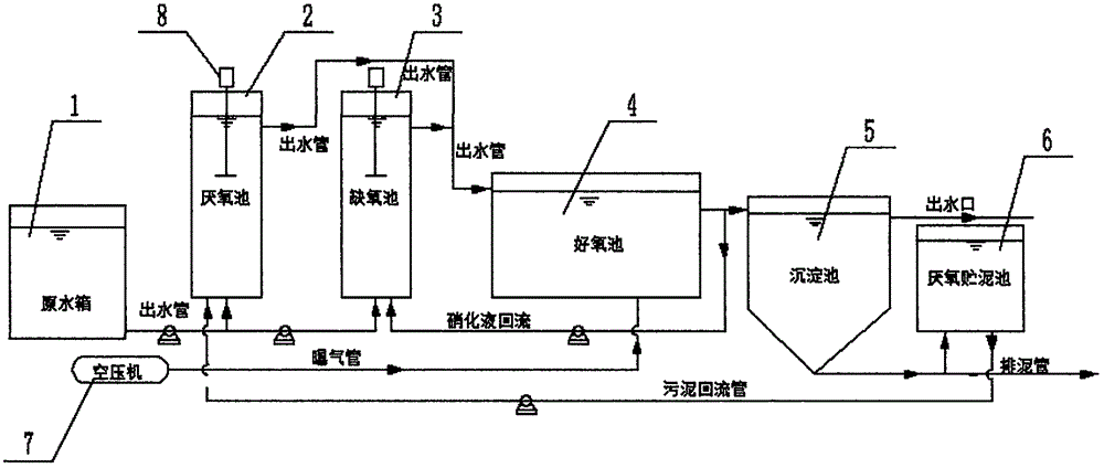
[0022] Step 1, the raw sewage enters the anaerobic pool 2 and the anoxic pool 3 according to the volume distribution ratio of 5:5, and the raw sewage CODCr concentration, TN concentration, NH3-N concentration, TP concentration, water temperature, anaerobic pool 2 and anoxic pool The HRT of Pool 3 was determined to be 396mg / L, 36mg / L, 34mg / L, 3mg / L, 28°C, 1.89h, and 0.94h, respectively;

[0023] Step 2, the aerobic pool 4 receives the mud-water mixture discharged from the anaerobic pool 2 and the anoxic pool 3, and the HRT, DO concentration and temperature of the aerobic pool 4 are respectively determined to be 1.85h, 2mg / L and 28°C;

[0024] Step 3, the mud-water mixture discharged from the aerobic tank 4 enters the sedimentation tank 5 and the anoxic tank 3 respectively according to the volume distribution ratio of 1:2.5, and the sedimentation time of the sedimentation tank 5 is determined to be 1 hour;

[0025] Step 4: After the mud-water separation is carried out in the sed...

Embodiment 2

[0029] Step 1, the raw sewage enters the anaerobic pool 2 and the anoxic pool 3 according to the volume distribution ratio of 5:5, and the raw sewage CODCr concentration, TN concentration, NH3-N concentration, TP concentration, water temperature, anaerobic pool 2 and anoxic pool The HRT of Pool 3 was determined to be 512mg / L, 64mg / L, 52mg / L, 9mg / L, 28°C, 1.89h, and 0.94h, respectively;

[0030] Step 2, the aerobic pool 4 receives the mud-water mixture discharged from the anaerobic pool 2 and the anoxic pool 3, and the HRT, DO concentration and temperature of the aerobic pool 4 are respectively determined to be 1.85h, 2mg / L and 28°C;

[0031] Step 3, the mud-water mixture discharged from the aerobic tank 4 enters the sedimentation tank 5 and the anoxic tank 3 respectively according to the volume distribution ratio of 1:2.5, and the sedimentation time of the sedimentation tank 5 is determined to be 1 hour;

[0032] Step 4: After the mud-water separation is carried out in the sed...


PUM


Abstract

The invention discloses a multipoint water-in sludge in-situ reduction synchronous coupling nitrogen and phosphorus removal method which comprises the following specific steps: (I) feed ing raw sewage into an anaerobic tank and an anoxic tank respectively according to a volume ratio of 5:5; (II) receiving the sludge-water mixture discharged by the anaerobic tank and anoxic tank by an aerobic tank; (III) feeding the sludge-water mixture discharged by the aerobic tank into a sedimentation tank and the anoxic tank according to a volume ratio of 1:2.5; (IV) performing sludge-water separation by the sedimentation tank, directly discharging the supernatant out of the treatment system, and dividing the sedimentation sludge into two parts, wherein one part is 95% of sedimentation sludge by volume which enters an anaerobic sludge storage tank, and the other part is 5% of sedimentation sludge by volume which is discharged by a sludge discharge pipe in a form of excess sludge; and (V) after endogenous anaerobic digestion of the sedimentation sludge in the anaerobic sludge storage tank, enabling the digestive mixed liquid to flow back into the anaerobic tank. The method disclosed by the invention has the following beneficial effects: based on in-situ reduction of sludge yield, the nitrogen and phosphorus removal efficiency of the sewage biological treatment technology can be effectively improved.

Description

technical field [0001] The invention relates to the technical field of sludge treatment, in particular to a multi-point water-influent sludge in-situ reduction synchronous coupling denitrification and phosphorus removal method. Background technique [0002] In the process of urban sewage treatment, not only strict requirements are put forward for the discharge of nitrogen and phosphorus, but also strict regulations are put forward for the discharge of sludge. [0003] Most of the modern sludge treatment methods use sludge concentration, sludge digestion and sludge dehydration to treat and reduce the sludge generated in the sewage treatment process. Most of the sludge treatment and disposal technologies and methods focus on terminal treatment. A series of environmental and technical problems will arise at the same time as the huge investment, which restricts the effective implementation of the final disposal of sludge. The treatment and disposal of sludge has become a major p...

Claims


Application Information

Patent Timeline
IPC IPC(8): C02F3/30C02F11/04C02F9/14
CPCC02F1/52C02F3/302C02F11/04C02F2101/16C02F2101/163
Inventor 李思敏徐宇峰唐锋兵张炜时真男王星朱冠男刘元慧
Owner HEBEI UNIV OF ENG
Features
  • Generate Ideas
  • Intellectual Property
  • Life Sciences
  • Materials
  • Tech Scout
  • Unparalleled Data Quality
  • Higher Quality Content
  • 60% Fewer Hallucinations
Learn More