
Gear Quenching Treatment Device

A processing device and gear technology, used in quenching devices, heat treatment furnaces, heat treatment equipment and other directions, can solve problems such as difficulty in salvaging, and achieve the effect of easy operation and improved processing quality

Active Publication Date: 2018-03-20
盐城伟一汽车配件有限公司
View PDF5 Cites 0 Cited by
  • Summary
  • Abstract
  • Description
  • Claims
  • Application Information

AI Technical Summary

Problems solved by technology

[0004] The present invention intends to provide a gear quenching treatment device to solve the problem that the gear is difficult to salvage after quenching

Method used


Image

  • Gear Quenching Treatment Device
  • Gear Quenching Treatment Device
  • Gear Quenching Treatment Device

Examples


Embodiment Construction

[0021] The present invention is described in further detail below by specific embodiments:

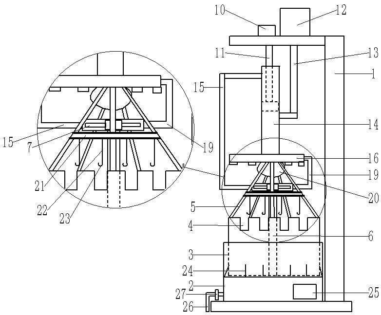
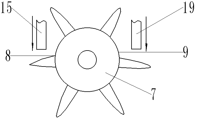
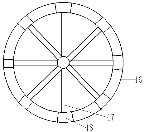
[0022] Reference numerals in the accompanying drawings include: frame 1, quenching cylinder 2, oil cylinder 3, clamping groove 4, strut 5, central shaft 6, impeller 7, first side 8, second side 9, first Cylinder 10, first piston rod 11, second cylinder 12, second piston rod 13, pipeline 14, reverse blowing pipe 15, turntable 16, chute 17, limit block 18, forward blowing pipe 19, elastic airbag 20 , Ring 21, elastic rope 22, hook 23, scraper 24, freezer 25, drain pipe 26, valve 27, gear 28.

[0023] The example is basically as figure 1 Shown: gear quenching treatment device, including frame 1, frame 1 is provided with quenching cylinder 2, the inner side wall of quenching cylinder 2 is provided with threads, quenching cylinder 2 is threadedly connected with oil cylinder 3, and quenching cylinder 2 is filled with For the cooling liquid, the inner side wall of the quenching cylinder 2 i...


PUM


Abstract

The invention relates to the technical field of machining of gears and discloses a gear quenching treatment device. The gear quenching treatment device comprises a rack which is provided with a quenching cylinder and an oil cylinder; the oil cylinder is provided with clamping grooves and supporting rods; a center shaft is arranged in the oil cylinder and is provided with an impeller which is provided with a first side portion and a second side portion, and the first side portion and the second side portion are symmetrical; a first cylinder and a second cylinder are arranged above the impeller; the first cylinder is provided with a first piston rod; a pipeline is arranged below the first cylinder; the second cylinder is provided with a second piston rod which is connected with the pipeline; the first piston rod and the pipeline are in clearance fit with each other; a reverse-direction gas blowing pipe is arranged on the pipeline; the other end of the reverse-direction gas blowing pipe faces the first side portion; a rotating disk is arranged at the lower end of the pipeline and is connected with a forward-direction gas blowing pipe; the other end of the forward-direction gas blowing pipe faces the second side portion; the rotating disk is provided with a slide groove; the supporting rods are connected in the slide groove in a sliding manner; an elastic gas bag is arranged below the rotating disk and is located in the middles of the supporting rods; and the exteriors of the supporting rods are provided with elastic rings which are provided with hooks. By means of the gear quenching treatment device, the problem that a gear is difficult to salvage after being quenched can be solved.

Description

technical field [0001] The invention relates to the technical field of gear processing, in particular to a gear quenching treatment device. Background technique [0002] Quenching cooling is an important process in gear production. It has a significant impact on the accuracy and quality of gears. Improvements are made in terms of clamping method, quenching medium state and quenching equipment, and strive to achieve uniform cooling of gears, which can greatly reduce gears. deformation amount and improve its deformation regularity. Quenching quality plays an important role in improving gear quality, labor productivity, and production environment. The heat treatment industry no longer regards quenching and cooling equipment as an insignificant auxiliary equipment, but regards it as a key equipment related to product quality and enterprise competitiveness. [0003] At present, when the gear is quenched, the gear is usually directly transferred to the oil tank or water tank by ...

Claims


Application Information

Patent Timeline
Patent Type & Authority Patents(China)
IPC IPC(8): C21D9/32C21D1/63
CPCC21D1/63C21D9/32Y02P10/20
Inventor 曾义杰
Owner 盐城伟一汽车配件有限公司
Learn More